Introduction
Stimulus groups are a special kind of ROI group that define a parametric path instead of a 3D volume. A stimulus group is comprised of multiple ROIs that define a continuous sequential laser path. Multiple groups can be defined and stored in the Photostimulation interface. Once the groups are defined, the Triggering Stimulus Patterns article describes how to go about commanding them.
Designing Stimulus Patterns
Stimulus groups allow complete freedom in designing the path for the laser to take. Best practices should be followed to ensure desired results. A stimulus pattern is comprised of a sequence of stimulus functions, each of which can be parameterized with position, size, rotation, laser power, number of repeats, parametric function, and custom parameters for the parametric function. The stimulus function can be chosen from a set of built in or custom stimulus functions.
A typical stimulus pattern begins with the laser at the parking position to minimize exposure of the sample to laser light (even with the pockels cell blanked). Time must be given to allow the laser to travel from the parking position to the first cell (or ROI) to stimulate. A parametric stimulus function can then be chosen for the given cell with parameters such as laser power and duration. Finally the laser should be returned to the parking position. A stimulus group to stimulate one cell would therefore have three ROIs:
- Pause function
- Stimulation function (ex: logspiral)
- Park function
If it is desired to stimulate multiple ROIs in one pattern, a pause should be inserted between stimulations to allow transition time, IE:
- Pause function
- Logspiral function
- Pause function
- Sinesquare function
- Pause function
- Logspiral function
- Park function
The pauses between stimulations are important because the galvo's require time to travel between ROIs. Without the pauses (or if the pauses are too short), the pockels cell will be open while the galvo is still traveling to the desired ROI, causing light exposure to the wrong part of the sample. If too large of a change in position is commanded without adequate transit time, or if the stimulus pattern is too demanding of performance from the galvo's, the galvo controller may reset, causing a momentary loss of galvo position control. It is therefore important to carefully design the stimulus pattern to avoid this and test the pattern to make sure the results are desirable. The best way to test for desired results is using the monitoring and logging feature to verify proper response from the galvos.
Using the Stimulus Editor
To create stimulus groups, launch the PHOTOSTIMULATION CONTROLS interface from the MAIN CONTROLS interface. The list on the left shows all stimulation patterns that have been defined. Click the new button to create a new empty stimulus group. With it selected, click the edit button to launch the stimulus editor. In the stimulus editor, an image can be copied in to serve as a context for designing the stimulus pattern. You can show a context image from the legend by turning on the live image, taking a snap shot, or loading an image from a tiff file.
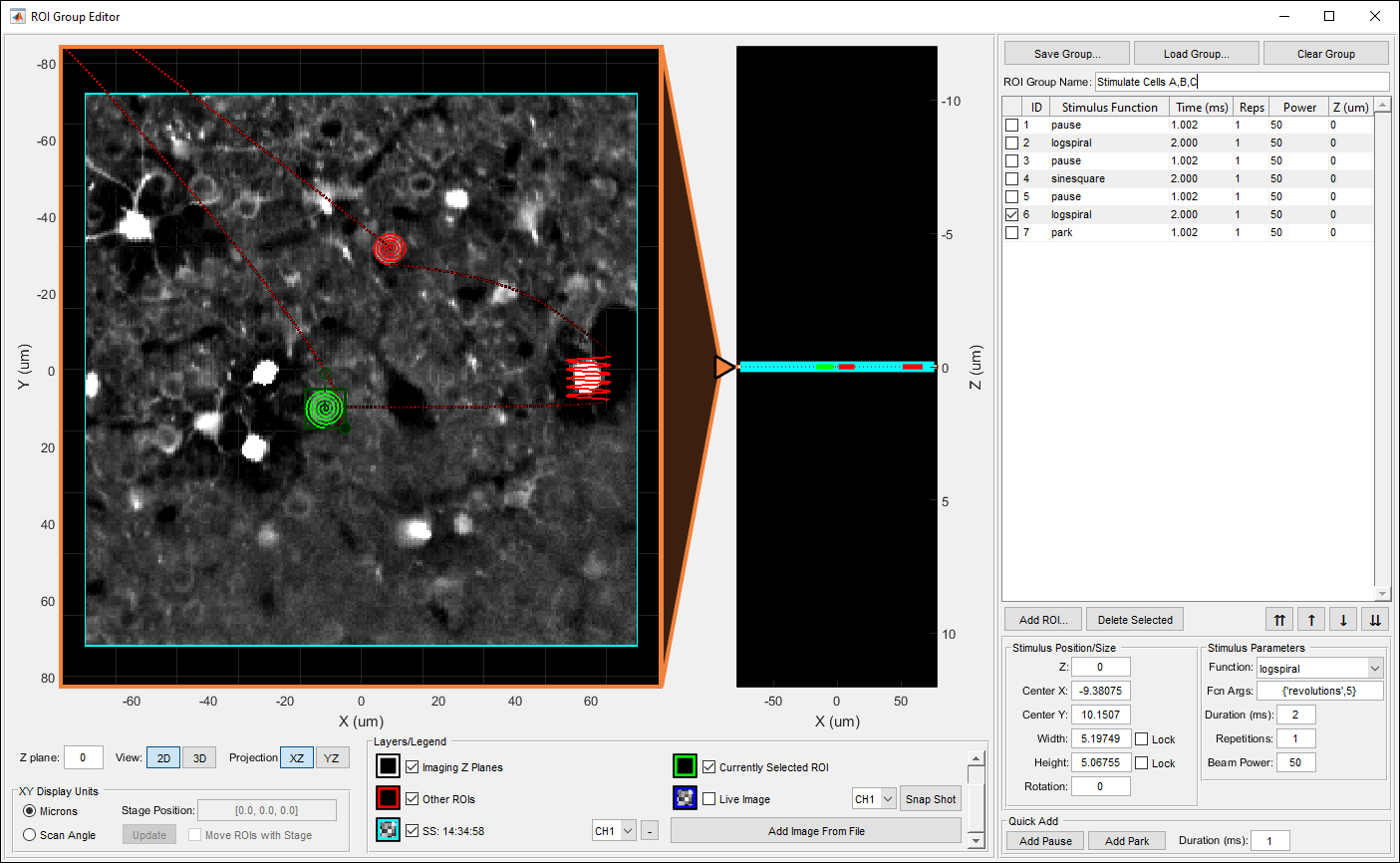
To add a stimulus function, click the Add ROI... button under the table display. You select parameters for the stimulus function from the panel in the bottom right then draw the desired function in the main view. The Quick Add panel in the bottom right can also be used to easily add pause and park functions. The sequence of stimulus functions is displayed in the table view. The controls below can be used to reorder or remove functions. Select a stimulus function in the table or in the main view to view its parameters in the bottom right. A complete reference for the stimulus editor interface can be found in the window reference guide. The screen shot below shows an example of designing a stimulation pattern to target three cells.
The following video demonstrates using the Stimulus editor to create a stimulus pattern:
Using SLM Patterns
When using a scan system that incorporates an SLM, stimulus patterns can be created that simultaneously excite multiple points within a 3D FOV. You can adjust the beam power weight factor of each point if non uniform power distribution between points is desired. If the scan system has a galvo pair in series with the SLM, the galvos can be utilized to steer the middle of the SLM pattern. This is important because most optical setups give the SLM limited FOV. The galvos can therefore effectively point the center of the SLM FOV to a location near the desired points to excite. The galvos can also be used to combine the multiple point generation with a scanned pattern, turning each point into a scan. Currently, only one SLM pattern can be specified for a stimulus group. That pattern will be generated for the duration of the stimulus function.
Using the Stimulus Editor with SLM Patterns
SLM patterns can be created by selecting "SLM pattern" from the function dropdown in the New Stimulus Function panel. Then proceed to click the desired points to stimulate in the display area. Each click will create another point. When done adding points click "Done" under the table on the right. To go back into point selection mode click "Add Points." The table on the right allows you to adjust the XYZ position and beam power weight factor for each point. The scanner FOV outline will indicate the area that the SLM is capable of addressing. The bounds of the FOV can be moved, which will adjust where the galvos will point during the pattern generation. Since most optical setups give the SLM limited range, the FOV should be moved so that all points that you desire to generate are within the FOV. If you have a zero order beam block in the path and have indicated so in the configuration, the non addressable area in the center of the SLM FOV is indicated. Avoid putting points to generate within this area. If you want to move the points together with the FOV, hold down the shift key while dragging the FOV.
If you want to combine the point generation with a galvo scan, select the desired scan function from the dropdown. You can adjust the size of the scan function in the display area. Just like regular stimulus functions, custom arguments can be edited for the given function. When finished editing the SLM pattern, click "Done" in the bottom right. To return to pattern editing mode, selected the desired stimulus function and click "Edit SLM Pattern" in the Selected Stimulus Function Properties panel.
And existing stimulus function can also be turned into an SLM pattern by selecting "SLM pattern" from the function dropdown in the Selected Stimulus Function Properties panel. The previously selected stimulus function will be set as the scan function and the pattern will start with one point. Enter SLM pattern editing mode to add more points and change parameters.
After returning to the regular stimulus editing mode, SLM patterns are depicted by showing the points being generated by the SLM connected with a dotted line to the point or scan function that the galvos will be executing. If you click and drag the function, it will adjust the position the galvos will point at during the generation, while keeping the points to generate constant. If you want to move the points to generate with the galvo position, hold down "shift" while dragging the function.