Regions of Interest/Stimulus Editor Panel
Overview
The ROI/Stimulus Group Editor is used for defining ROI's for imaging, photostimulation, and image analysis. The interface facilitates designing 3D regions and scan paths using collected images as a reference.
Imaging ROI groups consist of one or more 3D ROIs, which are defined by 2D scanfields. You can find a complete description of multiple region of interest imaging in the following concepts guide articles:
Stimulus groups are special cases of ROI groups where scanfields are parametric 2D stimulation paths instead of fields to raster scan. More details about photostimulation and stimulus groups can be found in the following articles:
ROI Display
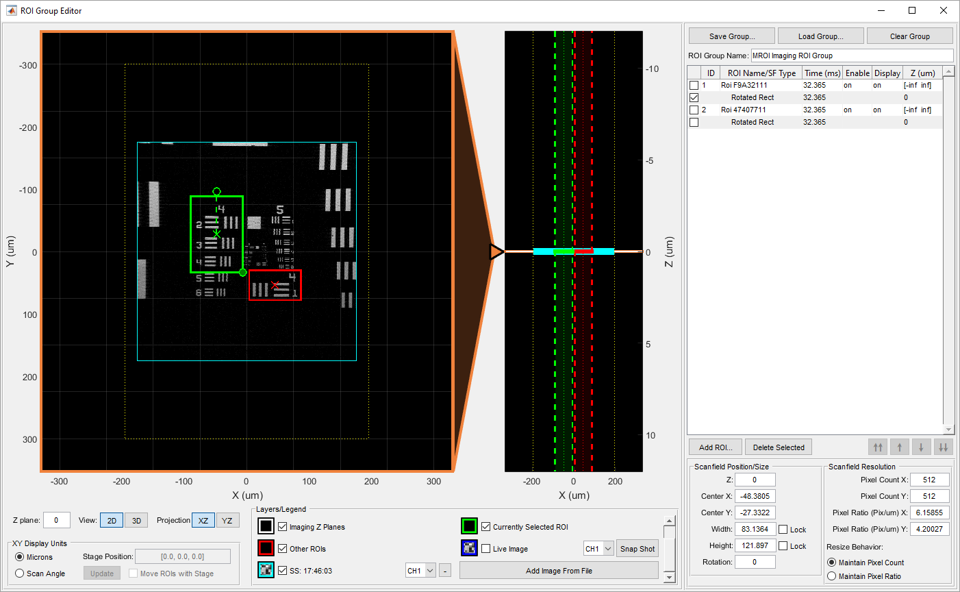
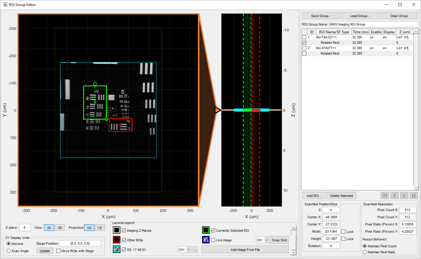
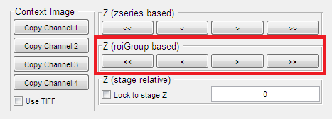
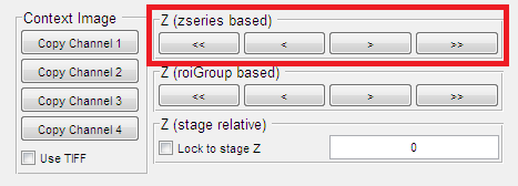
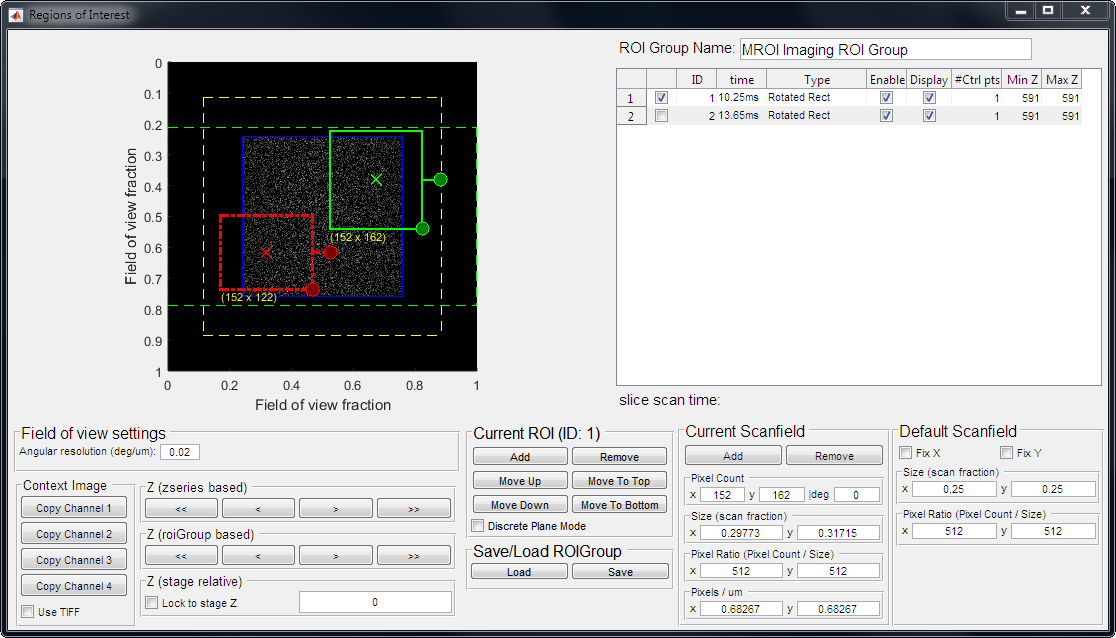
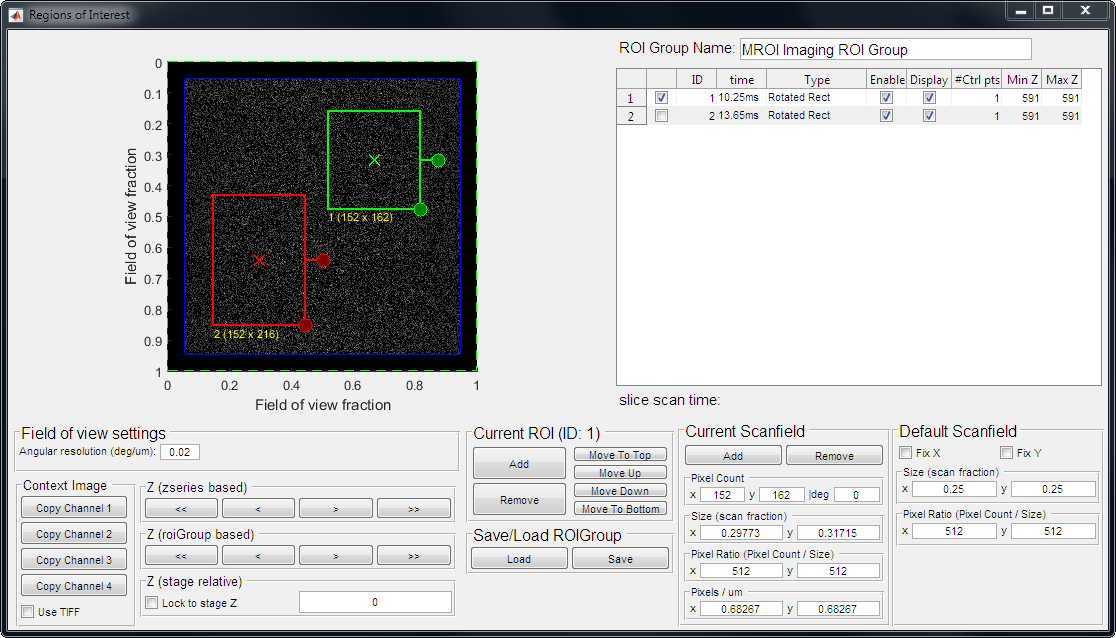
The main display contains a number of different elements identified by the legend at the bottom. The display can be switched between 2D and 3D viewing modes. In 2D mode the main display shows data at the current Z position with an accompanying side projection display at the right. The side projection can be switched between XZ and YZ modes with the controls below. The pointer between the main view and the projection view can be used to move the z plane which the main view is currently showing. The main view and side projection view both support mouse click and drag to pan and mouse wheel zoom. If you hold shift while using the mouse wheel (or if the mouse is hovering over the z control slider between the main and projection view) it will move the current Z position. The ROI display includes the following elements, all of which can be shown/hidden using the check boxes in the legend.
| Scanner Field of View | This shows a representation of the XY area that the scan mirrors are capable of addressing. All ROIs must stay within these boundaries |
| Editor Z Plane | In the side projection view, this shows an indication of what point in Z the main view is currently displaying |
| Imaging Z Planes | In the side projection view, these lines indicate where images will be taken using the current stack/volume acquisition settings |
| Currently Selected ROI | The ROI/scanfield currently selected for editing |
| Other ROIs | Other non-selected ROIs in the current ROI group |
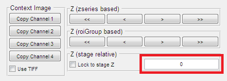
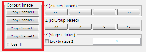
Live Image | A context image that updates in real time from the currently active video stream. The drop down allows selecting which channel to display and the Snap Shot button allows capturing the current context image |
| Additional Context Images | Additional context images that have been added to the view either by taking a snap shot of the live image or by loading a context image from a file |
In addition to the legend, the bottom panel contains additional view controls:
| Z plane | Indicates what point in Z the main view is currently displaying |
| View (2D/3D) | Switches the main view between 2D and 3D modes |
| Projection (XZ/YZ) | Select the XY dimension used for the side projection view |
| XY Display Units (Microns, Scan Angle) | Select the units used for XY coordinates throughout the interface |
ROI Group Table/ROI Group Controls
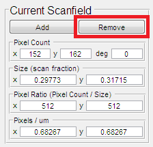
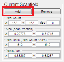
The right hand side of the interface displays information about the ROI group currently being edited. The controls at the top operate on the entire ROI group:
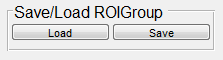
| Save Group | Save the current ROI group to a *.roi file |
| Load Group | Clears the contents of the ROI group that is currently being edited and replaces them with the ROIs from the selected file. |
| Clear Group | Clears the contents of the ROI group that is currently being edited |
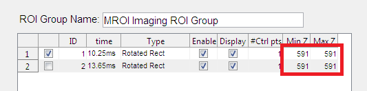
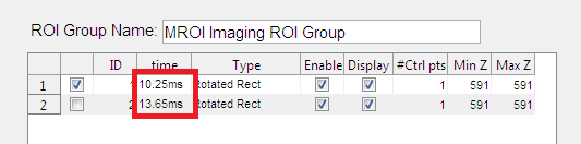
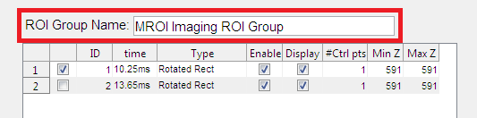
| ROI Group Name | Specifies a name for the current ROI group |
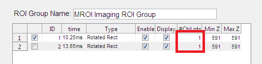
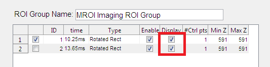
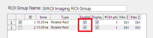
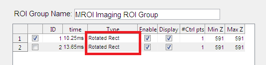
The ROI table displays information about all the ROIs in the ROI group and all the scanfields within each ROI. This table displays different information depending on whether you are currently editing an imaging ROI group, stimulation pattern, or analysis ROI group.
Imaging ROI Table
For each ROI in the group and each scanfield in each ROI, the following information is listed in the table
| ID | Numeric identifier of the ROI |
| ROI Name/Scanfield Type | For ROIs, the name. If a name has not been specified, a randomly generated unique identifier is used. For scanfields, type type of field |
| Time | For ROIs, the time required to scan the largest scanfield in the ROI. For scanfields, the time required to image the field. This value is displayed in milliseconds |
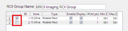
| Enable | For ROIs, indicates if the ROI is enabled for imaging. When disabled the ROI will not be scanned |
| Display | For ROIs, indicates if the ROI will be shown in the display window. When disabled, the ROI will still be scanned but will not be displayed in the live image |
| Z | For ROIs, indicates the range over Z that the ROI spans. For scanfields, indicates the Z position of the scanfield. |
Stimulation Pattern Table
For each stimulus function in the pattern, the following information is listed in the table
| ID | Numeric identifier of the stimulus pattern |
| Stimulus Function | Selected stimulus function |
| Time | The duration specified to output the stimulus function |
| Repetitions | The number of times to repeat the stimulus function |
| Power | The laser power speficied for the stimulation function |
| Z | The Z position of the stimulation function |
Analysis ROI Table
For each ROI in the group and each scanfield in each ROI, the following information is listed in the table
| ID | Numeric identifier of the ROI |
| Analysis Type | The type of analysis to be performed |
| Channel | The channel on which to perform the analysis |
| Threshold | The threshold to compare the integration with for output of a logic state. |
| Processor | The processor used to perform the analysis |
| Z | For ROIs, indicates the range over Z that the ROI spans. For scanfields, indicates the Z position of the scanfield. |
ROI Table Controls
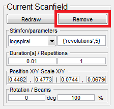
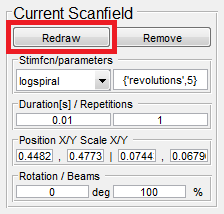
Below the ROI table, there are controls for adding, removing, and reordering ROIs
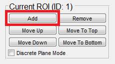
| Add ROI | Opens the New ROI Panel detailed in the next section |
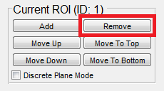
| Delete Selected | Deletes the selected item in the table |
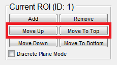
| Move to Top | Moves the selected ROI to the top of the list |
| Move Up | Moves the selected ROI up in the list |
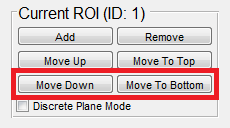
| Move Down | Moves the selected ROI down in the list |
| Move to Bottom | Moves the selected ROI to the bottom of the list |
New ROI Panel
To access the new ROI panel, click the Add ROI button or use the hotkeys detailed in a later section. With the New ROI panel open there are multiple ways to create a new ROI. You can click and draw a ROI in the main view, create using position and size entered in the text fields, or use the cell picker.
Drawing ROIs in the Main View
To draw an ROI in the main view, select Top Left Rectangle or Center Point Rectangle depending on how you want to draw the ROI. Click and drag in the main view to draw the ROI in the desired location. If you click and release without dragging, an ROI will be created at the position you clicked using the default size entered in the new ROI panel. If the lock checkbox is selected for either width or height, the corresponding dimension will be constrained to the entered value while dragging. After drawing the ROI, if the Draw Multiple checkbox is off, the new ROI will be selected and the New ROI panel will close to be replaced by the Selected ROI panel showing propertied of the ROI that was just created. If the Draw Multiple checkbox is on, the New ROI panel will stay open allowing you to quickly draw multiple ROIs.
Create ROI Using the Entered Position
To create an ROI by entering the position, Top Left Rectangle or Center Point Rectangle must be selected. You can then manually enter values for center position, width, height, and rotation. After entering the desired position, click the Create Using Defaults button to create the ROI. After creating the ROI, if the Draw Multiple checkbox is off, the new ROI will be selected and the New ROI panel will close to be replaced by the Selected ROI panel showing propertied of the ROI that was just created. If the Draw Multiple checkbox is on, the New ROI panel will stay open allowing you to quickly add multiple ROIs.
Create ROI using the Cell Picker
Using the cell picker is detailed in a later section.
Additional Parameters
In addition to the position and size, additional parameters for the new ROI can be specified on the right hand side of the New ROI panel. The available parameters depend on what kind of ROI group is being edited.
Imaging ROI Parameters
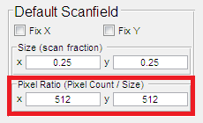
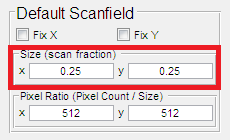
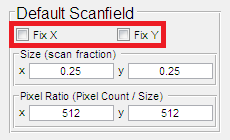
For imaging ROIs, the pixel resolution can be specified. This can be done in terms of pixel count or pixel ratio. If pixel ratio is used, the pixel count will be set by the size of the new ROI.
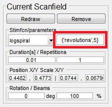
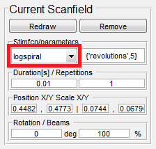
Stimulus Function Parameters
For stimulus groups, the following parameters can be specified:
| Function | The parametric function that defines the scan path for this stimulus function |
| Function Arguments | Custom arguments to use as parameters for the parametric function |
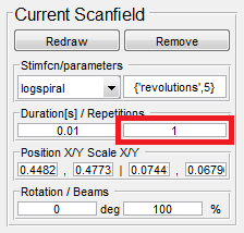
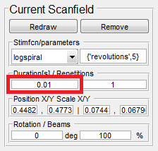
| Duration | Duration of the function |
| Repetitions | Number of times to repeat the function |
| Beam Power | Laser power to use while outputting the function |
Analysis ROI Parameters
For analysis ROIs, the following parameters can be specified:
| Channel | The channel to perform the analysis |
| Threshold | The threshold to compare the integration with for output of a logic state |
| Processor | The processor used to perform the analysis |
Selected ROI/Scanfield Properties Panel
If there is an item selected in the ROI table, the bottom right panel will show properties of the selected item. The following properties will be available for the indicated type of selected item:
Imaging ROI
| ROI Name | Display name for the ROI |
| Unique ID | Unique identifier for the ROI assigned at creation |
| Enabled | Indicates if the ROI is enabled for imaging. When disabled the ROI will not be scanned |
| Show in Image Display | Indicates if the ROI will be shown in the display window. When disabled, the ROI will still be scanned but will not be displayed in the live image |
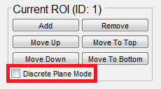
| Discrete Plane Mode | Indicates if the ROI should be a discrete plane ROI |
| Number of Scanfield Control Points | Indicates number of scanfields in the ROI |
| ROI Minimum Z | Indicates the minimum Z position contained by the ROI |
| ROI Maximum Z | Indicates the maximum Z position contained by the ROI |
| Edit/Add Scanfield At Current Z | If there is a scanfield defined for this ROI at the current editor Z plane, this button will select it to show/edit its properties. If there is not a scanfield at the current Z plane, this button will add one to the ROI and select it for editing |
| ROI Specific Power Controls | These parameters allow specifically controlling the power of an ROI. If any of the values are unset, the parameters from the POWER CONTROLS interface are used like normal |
| Powers | Laser power. If there are multiple pockels cells, a value for each should be entered separated by commas |
| Enable P/z Adjust | Enter 1 or 0 (to indicate on or off) to control whether power/depth adjustment is enabled for this ROI |
| Length Constants | Length constant for each pockels cell for power/depth adjustment |
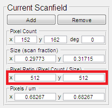
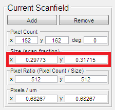
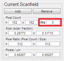
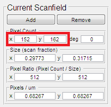
Imaging Scanfield
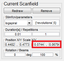
| Z | Z position of the scanfield |
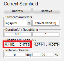
| Center X/Y | The position of the center of the scanfield |
| Width/Height | The size of the scanfield |
| Rotation | The rotation angle of the scanfield |
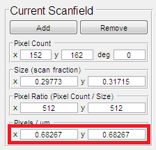
| Pixel Count (X/Y) | Pixel count for the scanfield |
| Pixel Ratio (X/Y) | Ratio of pixels to scanfield size |
| Resize Behavior | Indicates whether pixel count or pixel ratio should be held constant as ROI is resized |
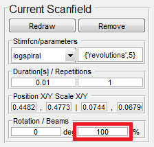
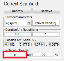
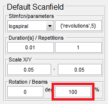
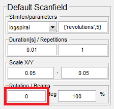
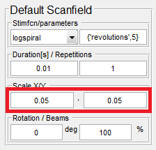
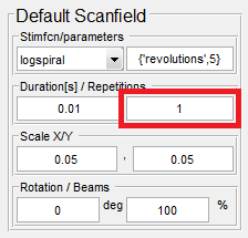
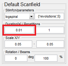
Stimulus Function
| Z | Z position of the scanfield |
| Center X/Y | The position of the center of the scanfield |
| Width/Height | The size of the scanfield |
| Rotation | The rotation angle of the scanfield |
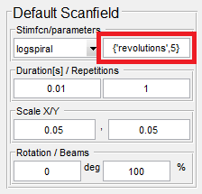
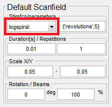
| Function | The parametric function that defines the scan path for this stimulus function |
| Function Arguments | Custom arguments to use as parameters for the parametric function |
| Duration | Duration of the function |
| Repetitions | Number of times to repeat the function |
| Beam Power | Laser power to use while outputting the function |
Analysis ROI
| ROI Name | Display name for the ROI |
| Unique ID | Unique identifier for the ROI assigned at creation |
| Enabled | Indicates if the ROI is enabled for analysis. When disabled the ROI will not be processed |
| Show in Integration Display | Indicates if the ROI will be shown in the integration display window. When disabled, the ROI will still be processed but will not be displayed in the live integration trace |
| Discrete Plane Mode | Indicates if the ROI should be a discrete plane ROI |
| Channel | The channel on which to perform the analysis |
| Threshold | The threshold to compare the integration with for output of a logic state |
| Processor | The processor used to perform the analysis |
| Number of Scanfield Control Points | Indicates number of scanfields in the ROI |
| ROI Minimum Z | Indicates the minimum Z position contained by the ROI |
| ROI Maximum Z | Indicates the maximum Z position contained by the ROI |
| Edit/Add Scanfield At Current Z | If there is a scanfield defined for this ROI at the current editor Z plane, this button will select it to show/edit its properties. If there is not a scanfield at the current Z plane, this button will add one to the ROI and select it for editing |
Stimulation Quick Add Panel
When editing stimulation patterns, it is important to put pauses between stimulation functions to allow the scanner time to transition from one ROI to another. The quick add panel provides the means to do so quickly.
| Add Pause | Adds a pause function to the end of the stimulus pattern using the specified duration |
| Add Park | Adds a park function to the end of the stimulus pattern using the specified duration |
| Duration | Specifies the duration to use when adding a pause or park using the Quick Add panel |
Using the Cell Picker
The cell picker allows you to select ROIs from a context image using image segmentation to identify features in the image. The cell picker is available for creating imaging ROIs, stimulus patterns, and analysis ROIs. In order to use the cell picker, you must have a context image currently showing. You can obtain a context image by showing the live context image, taking a snapshot, or loading an image from a file. The cell picker can be accessed from the New ROI panel by selecting Cell Picker. Once in cell picker mode, You can choose a selection mode. The selection mode selects which segmentation routine is used to identify cells in the image. The built in modes are Disk, Annular, and Manual (manual mode does not use segmentation; it will just use a default cell size around where the mouse is clicked). You can also define your own custom segmentation routine. Once the desired selection mode is chosen, click anywhere within a context image in the main view to find a cell at the clicked point. If the segmentation routine finds a cell, it will be indicated with a green highlight. At this point, you can continue clicking to identify more cells. The currently selected cell can be increased in size using the Dilate button or shrunk using the Erode button. Once all the desired cells are selected, click the Add Selected Cells button to create the ROIs.
Depending on the type of ROI group currently being edited, additional options are available for how the ROIs are created:
Imaging ROI Cell Picker Options
| ROI Margin | Indicates how much larger than the cell to create the ROI |
| Create as Discrete Plane ROI | Indicates that the created ROIs should be discrete plane ROIs |
Stimulation Function Cell Picker Options
| Pause Between Stims | Indicates duration of a pause function to add between stimulation functions for selected cells |
Imaging ROI Cell Picker Options
| ROI Margin | Indicates how much larger than the cell to create the ROI |
| Create as Discrete Plane ROI | Indicates that the created ROIs should be discrete plane ROIs |
| Create with Mask | Indicates if the ROIs should be created with masks so that only the pixels identified from the segmentation routine will be included in the analysis |
Hotkeys
The following hotkeys are available in the ROI editor interfaace:
| "a" / "insert" | Open the New ROI panel |
| "d" / "delete" | Delete the selected item in the ROI table |
| "c" | Enter cell picker mode |
| "p" | If currently editing a stimulation pattern, adds a pause function using the quick add panel |
| "k" | If currently editing a stimulation pattern, adds a park function using the quick add panel |
| "escape" | Deselects any currently selected item and exits the New ROI and cell picker modes |
The following hotkeys are available when the New ROI panel is open
| "r" | Toggle between Top Left Rectangle and Center Point Rectangle modes |
| "c" | Enter cell picker mode |
| "m" | Toggle Draw Multiple option |
The following hotkeys are available when the New ROI panel is open in cell picker mode
| "a" / "insert" | End the cell pick session and create ROIs for the selected cells (same as clickind the Add Selected Cells button) |
| "d" | Dilate selected cell |
| "e" | Erode selected cell |
| "delete" | Delete selected cell |
| "m" | Cycle through cell picker selection modes |