ResScan Acquisition System
The ResScan acquisition system is the minimum hardware required for raster image scanning.
It consists of a PXIe chassis which is connected to a PC via a PCI Express card. The PXIe chassis has at least two cards installed:
- Digitizer: A FlexRIO card with a digitizer module attached.
- Scan Control DAQ: An X-Series DAQ board.
For Thorlabs systems, see Thorlabs Scope Wiring below
For all other systems, connect according to the schematic at right:
- Connect lines from PMT amplifiers to the analog inputs on the digitizer module.
- Connect the resonant mirror's Period Trigger to PFI0 on the breakout for the scan control DAQ.
- Connect the control line for the X Zoom to an analog output on the breakout for the scan control DAQ.
- Connect the control line for the Y Mirror to an analog output on the breakout for the scan control DAQ.
- Connect any necessary Acquisition Triggering (Start, Next, Loop) to PFI1-4. These connections are configured using the Triggers Contol.
- To configure a Shutter for ResScan, review the article Shutter Configuration

Beams
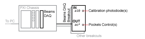
The Beams subsystem requires its own DAQ module. There are two supported configurations.
For both:
- connect calibration inputs to the desired analog input terminals.
- connect control lines to the desired analog outputs.
PXI-based
The relevant timing signals are communicated through the PXI backplane; no extra wiring is needed.
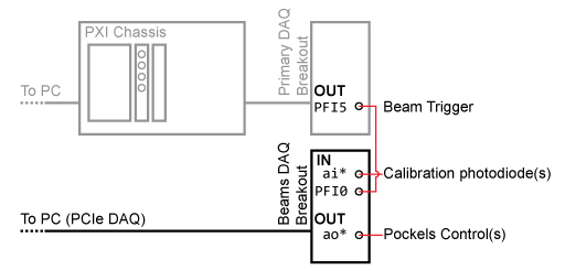
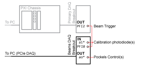
PCIe-based
Connect PFI5 of the scan control DAQ breakout box to the PFI terminal on the Beam DAQ board.
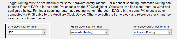
The settings for the routing of triggers are accessed in the Power Modulation (Beams) section of the ScanImage Machine Configuration Editor.
In this case, select "PFI0" for the Line Clock Input Terminal:
Fast Z
The Fast Z subsystem requires its own DAQ module. There are two supported configurations.
For both:
- connect the control line to the desired analog output.
PXI-based
The relevant timing signals are communicated through the PXI backplane; no extra wiring is needed.
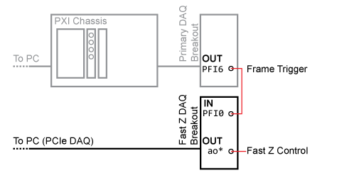
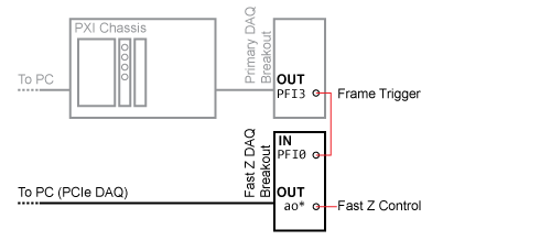
PCIe-based
Connect PFI6 of the scan control DAQ breakout box to the PFI terminal on the FastZ DAQ board.
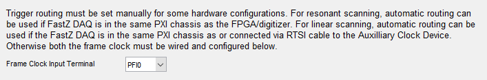
The settings for the automatic routing of the frame clock trigger for Fast Z is accessed in the FastZ Actuator Setup section of the ScanImage Machine Configuration Editor.
In this case, select "PFI0" for the Frame Clock Input Terminal:

Signals Summary
Timing Signals (DigitalIODevice)
Inputs (to DigitalIODeviceName)
| Signal | Description | DAQ Terminal |
|---|---|---|
| Period Trigger | Provided by resonant mirror driver as critical synchronization signal used for image formation. | PFI 0 |
| Start Trigger | A TTL transition will cause a running Acquisition Mode to start it's first Acquisition. | Specifed in Triggers |
| Next File Trigger | A TTL transition will cause a LOOP to start the next Acquisition. | Specifed in Triggers |
| Stop Trigger | A TTL transition will cause a running Acquisition to end. | Specifed in Triggers |
Outputs (from DigitalIODeviceName)
| Signal | Description | DAQ Terminal |
|---|---|---|
| Beam Clock | A TTL pulse generated on each line that controls when waveforms driving the Pockels cells begin. | PFI 5 |
Frame Clock | A TTL pulse generated at the start of each frame. | PFI 6 |
| Acq Trigger | A TTL pulse generated when an acquisition starts. Useful for responding to software-triggered acquisitions. | PFI 7 |
Analog Inputs
| Signal | Description |
|---|---|
| Channels 1-4 | Voltage inputs used for imaging, typically from the PMTs. |
| Beams | Voltage from a photodiode reporting the transmission through a Pockels cell. For calibration. Each Pockels cell requires an analog input channel. |
Analog Outputs
| Signal | Description |
|---|---|
| X Zoom | Control voltage specifying the scan amplitude of the resonant mirror. |
| Y Mirror | Control voltage specifying the deflection of the Y mirror. |
| Beams | Control voltage specifying for controlling a Pockels cell. Each Pockels cell requires one analog output channel. |
| Fast Z | Control voltage specifying the deflection of an objective positioner used for fast volume imaging. |
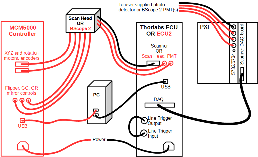
Thorlabs Scope Wiring
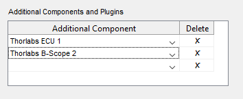
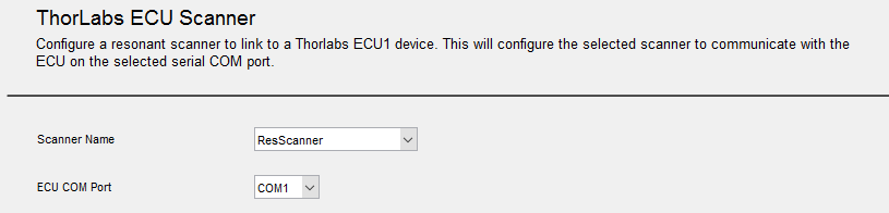
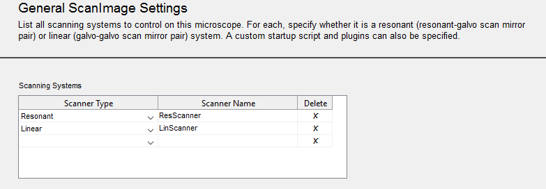
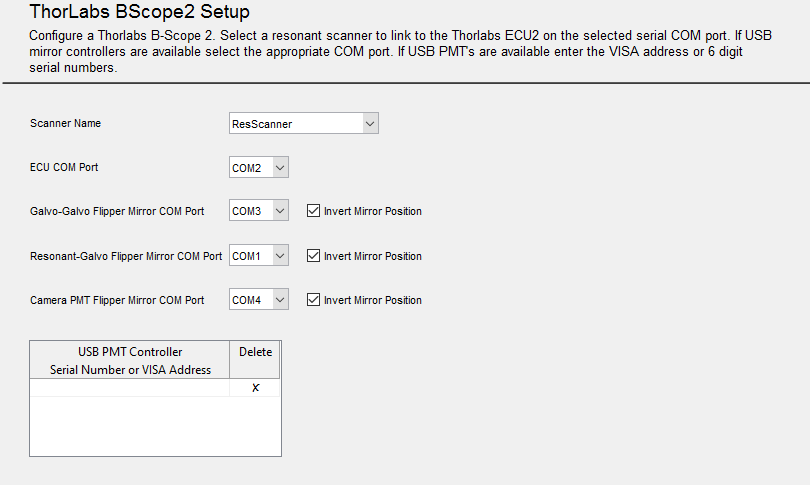
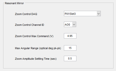
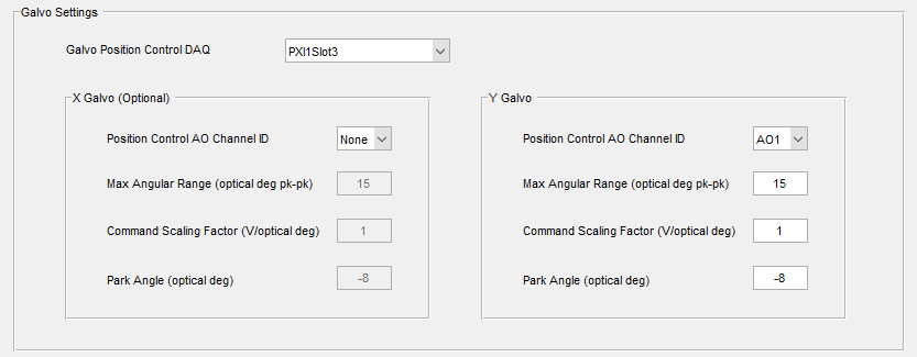
Steps to integrate a Thorlabs ECU1 or ECU2 (BScope 2) into a ScanImage 2016 system: Use the image below as a guide. Items in black apply to both ECU1 and ECU2/BScope 2 while items in red apply only to the ECU2/BScope 2. Start ScanImage 2016 and select the option to create a new machine data file. The ScanImage Machine Configuration Editor will be started. Beginning with the General ScanImage Settings section, enter settings information appropriately. To configure ThorLabs ECU and/or BScope 2, they must first be added within the ScanImage Machine Configuration Editor. In the General ScanImage Settings section, add "Thorlabs ECU 1" and/or "Thorlabs B-Scope 2" to the Additional Components and PlugIns table, depending on your hardware. The ScanImage Machine Configuration Editor will add settings sections, accordingl Select the ThorLabs ECU Scanner section In the ScanImage Machine Configuration Editor. Select the resonant scanning system you defined in the General ScanImage Settings section. Only scanners that have a "Resonant" Scanner Type are available in the Scanner Name dropdown list. Recap: Select the ECU COM Port of USB to serial adapter that installs when USB cord was plugged in. Use the device manager to determine this. Select the ThorLabs BScope2 Setup section In the ScanImage Machine Configuration Editor. Select the resonant scanning system you defined in the General ScanImage Settings section. Only scanners that have a "Resonant" Scanner Type are available in the Scanner Name dropdown list. Recap: Select the appropriate COM Ports for ECU, Galvo-Galvo Flipper mirror, Resonant-Galvo Flipper mirror, and Camera PMT Flipper mirror. See ThorLabs BScope2 Settings for additional setup information. Select the Scanner Settings section for the defined Resonant scanning system, In the ScanImage Machine Configuration Editor. The defined scanning system will appear in the section name. Enter the additional Resonant and Galvo mirror configuration. Resonant Mirror settings Select the name of the DAQ device where Thorlabs ECU is plugged in (found in NI MAX. (ex: 'PXI1Slot3')) in the Zoom Control DAQ. Defaults are provided by the system. Change default entries as needed. Galvo Mirror settings Defaults are provided by the system. Change default entries as needed. Wire the Thor ECU and ScanImage 2016 system
Start ScanImage
Configure ScanImage
As sections are configured, modify them appropriately then press Next. When the Additional Components section is reached, you can press Finish or Finish and Run ScanImage to save configured information to the given machine data file.
Machine configuration can be updated at a later time by selecting the Machine Configuration... option on the File Menu on the Main Controls panel.Integrate ThorLabs ECU and/or BScope 2 into ScanImage
A Thorlabs ECU Scanner Settings section is added if "Thorlabs ECU 1" is selected as an additional component; and a ThorLabs BScope2 Setup section is added if "Thorlabs B-Scope 2" is selected as an additional component.Configure Thorlabs ECU Scanner
Configure Thorlabs B-Scope 2
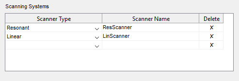
Configure Resonant Scanning System
