
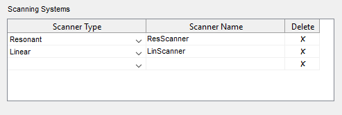
ScanImage 2015/2016 supports galvo/galvo scanning through the module 'LinScan'. LinScan replicates most of the features (triggering, timestamping) of the resonant scanning subsystem (ResScan), but utilizes National Instruments multifunction DAQ boards instead of the FlexRIO platform to acquire data and control the microscope. The recommended hardware for LinScan is a simultaneously sampled NI X-series DAQ board (e.g. NI PXIe/PCIe/USB-63xx). For backward compatibility to ScanImage 3.x, legacy hardware (e.g. NI-6110) is supported as well.
The LinScan module is subdivided into three logical devices: Signal Acquisition DAQ; Auxiliary Digital I/O DAQ; and Galvo Position Control DAQ. Settings for these devices are configured in the Scanner Settings for the associated Linear Scanning system (LinScanner, above), in the ScanImage Machine Configuration Editor. The settings map the logical devices onto the physical DAQ devices available in the computer. Multiple logical devices can be mapped onto the same physical. If the logical devices are mapped to separate physical devices, these devices need to be connected to each other via either a RTSI cable or they all need to be installed in the same PXI chassis.
| Logical Device | Comment | DAQ Requirements |
|---|---|---|
| Acquisition device | Uses analog inputs to acquire image data from the PMTs | For multi-channel input, analog inputs need to be simultaneously sampled. Sample rate ideally >= 1.25MHz |
| Galvo device | Uses analog outputs to control the positions of the X/Y Galvos | Requires at least two analog outputs |
| Auxiliary device | Utilizes trigger lines and counters to generate clocks, register triggers and generate hardware timestamps | Needs to be an NI X-series DAQ board (63xx) |
Example 1: NI-PXIe\USB 6356
| Dev1 (6356) | |
|---|---|
| Acquisition device: AIs simultaneously sampled, sample rate >= 1.25MHz | yes |
| Galvo device: has two analog outputs | yes |
| Auxiliary device: is NI X-series (63xx) | yes |
Since the NI-6356 fulfills the requirements for all the virtual devices, no additional hardware is required for LinScan in the Scanner Settings:
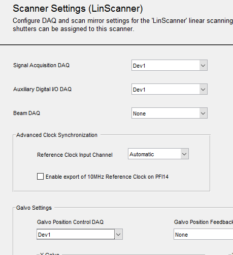
The Galvo device name is selected from the Galvo Position Control DAQ dropdown list.
The acquisition device name is selected from the Signal Acquisition DAQ dropdown list.
The auxiliary device name is selected from the Auxiliary Digital I/O DAQ dropdown list.
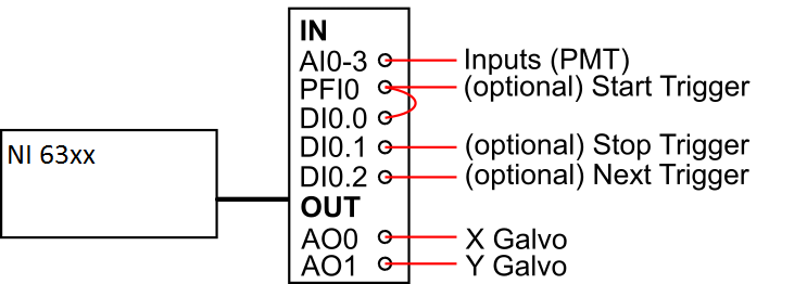
Wiring diagram for a NI PXIe\USB-6356.
Example 2: NI-6110 in combination with NI-6321
| Dev1 (6110) | Dev2 (6321) | |
|---|---|---|
| Acquisition device: AIs simultaneously sampled, sample rate >= 1.25MHz | yes | no |
| Galvo device: has two analog outputs | yes | yes |
| Auxiliary device: is NI X-series (63xx) | no | yes |
This allows two possible configurations in the Scanner Settings section of the ScanImage Machine Configuration:
Configuration 1 Configuration 2

The Galvo device name is selected from the Galvo Position Control DAQ dropdown list.
The acquisition device name is selected from the Signal Acquisition DAQ dropdown list.
The auxiliary device name is selected from the Auxiliary Digital I/O DAQ dropdown list.
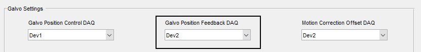
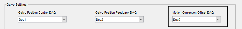
| Configuration 1 | Configuration 2 |
|---|---|
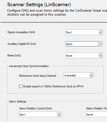
| Signal Acquisition DAQ = 'Dev1' Galvo Position Control DAQ = 'Dev1' Auxiliary Digital I/O Daq = 'Dev2' | Signal Acquisition DAQ = 'Dev1' Galvo Position Control DAQ = 'Dev2' Auxiliary Digital I/O Daq = 'Dev2' |
In Configuration 1, the analog inputs and analog outputs of Dev2 are unused by LinScan, so that Dev2 can also be used as the Beams or FastZ device.

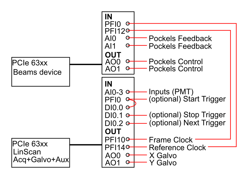
Wiring diagram for configuration 1. Since the analog inputs and analog ouputs of Dev2 (NI-6321) are unused, they can be configured to control a Pockels cell. See section 'Pockels Control'.
LinScan Pinout
Acquisition Device
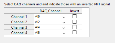
The standard PMT inputs for the Acquisition Device are channel AI 0-3. This configuration can be changed in the Scanner Settings of the ScanImage Machine Configuration.
For instance, to configure the PMT input channels as channels 0,2,4,6 instead of the standard channels 0,1,2,3, select the DAQ Channels as follows:
Galvo Device
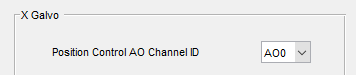
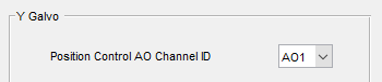
The control output for the X / Y Galvos can be configured in the Scanner Settings of the ScanImage Machine Configuration, by setting the Position Control AO Channel IDs.
X-Galvo Mirror Channel ID Y-Galvo Mirror Channel ID
Auxiliary Device
Outputs
| Outputs | |
|---|---|
| Frame Clock | PFI10 |
| 10MHz Reference Clock | PFI14* |
The frame clock is output on PFI10.
The 10Mhz Reference Clock is output on PFI14, only if the "Enable export of 10MHz Reference Clock on PFI14" checkbox is checked.
| Inputs | |
|---|---|
| Start Trigger | PFI0 -> port0/line0* |
| Stop Trigger | port0/line1 |
| Next Trigger | port0/line2 |
*PFI0 and port0/line0 need to be bridged to ensure proper time stamping of the start trigger
Shutter Control
To configure a shutter for LinScan, review the article Shutter Configuration. If using the Auxiliary DAQ to control the shutter, PFI12 is recommended for the digital output.
Pockels Control
Automatic Trigger Routing
No external trigger wiring between LinScan and the Beams DAQ board is required in the following cases
- The LinScan Auxiliary device and the Beams device are configured to operate on the same DAQ
- The LinScan Auxiliary DAQ and the Beams DAQ are installed in the same PXI chassis
- The LinScan Auxiliary DAQ and the Beams DAQ are connected via a RTSI bus, and the RTSI bus is correctly set up in NI-MAX
For the three cases above, all triggers are routed automatically.
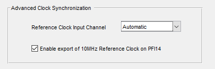
The settings for the automatic routing of triggers are accessed in the Power Modulation (Beams) section of the ScanImage Machine Configuration Editor.
In this case, select "Automatic Routing" for Line Clock, Frame Clock and Reference Clock input terminals:


Trigger Routing via RTSI bus: frame clock and reference clock are automatically routed over RTSI
Manual Trigger Wiring
In case the LinScan Auxiliary device and the Beams device are not connected via the PXI/RTSI bus, the LinScan frame clock and reference clock need to be wired to the Beams device.
| Trigger | Source | Destination |
|---|---|---|
| LinScan Frame Clock | LinScan Auxiliary board PFI10 | Beams board any free PFI (e.g. PFI12) |
| LinScan Reference Clock | LinScan Auxiliary board PFI14 | Beams board any free PFI (e.g. PFI0) |
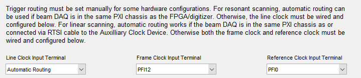
The settings for the automatic routing of triggers are accessed in the Power Modulation (Beams) section of the ScanImage Machine Configuration Editor.
In this case configure the settings:
- Set Line Clock Input Terminal to "Automatic"
- Set Frame Clock Input Terminal to "PFI12"
- Set Reference Clock Input Terminal to "PFI0"
External Trigger Wiring for Pockels Control
FastZ (Piezo) Control
Automatic Trigger Routing
No external trigger wiring between LinScan and the FastZ DAQ board is required in the following cases
- The LinScan Auxiliary device and the FastZ device are configured to operate on the same DAQ
- The LinScan Auxiliary DAQ and the FastZ DAQ are installed in the same PXI chassis
- The LinScan Auxiliary DAQ and the FastZ DAQ are connected via a RTSI bus, and the RTSI bus is correctly set up in NI-MAX
For the three cases above, all triggers are routed automatically so that the FastZ section in the Machine Data File can be configured as follows:
For the three cases above, all triggers are routed automatically.
The settings for the automatic routing of the frame clock trigger for Fast Z is accessed in the FastZ Actuator Setup section of the ScanImage Machine Configuration Editor.
In this case, select "Auto" for the Frame Clock Input Terminal:
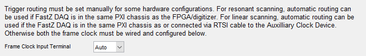

Automatic Trigger Routing for Piezo Control
Manual Trigger Wiring
In case the LinScan Auxiliary device and the FastZ device are not connected via the PXI/RTSI bus, the LinScan frame clock needs to be wired to the FastZ device:
| Trigger | Source | Destination |
|---|---|---|
| LinScan Frame Clock | LinScan Auxiliary board PFI10 | FastZ board any free PFI (e.g. PFI0) |
The settings for the automatic routing of the frame clock trigger for Fast Z is accessed in the FastZ Actuator Setup section of the ScanImage Machine Configuration Editor.
In this case, select "PFI0" for the Frame Clock Input Terminal:


External Trigger Wiring for Piezo Control