Linear Scanning Settings Panel
ScanImage creates a separate settings page for each Linear Scanner configured on the General ScanImage Settings page.
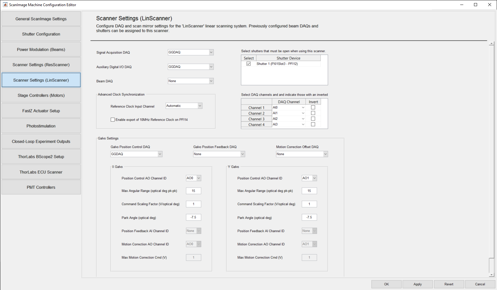
The defined Linear Scanner name will appear next to the Scanning Settings label in the page name.
In the display above, a linear scanner called "LinScanner" was defined as the name associated with a Linear Scanning System on the General ScanImage Settings page.
Top Panel Display Settings
| Signal Acquisition Daq | Select the NI DAQ board used for PMT channels input. |
| Auxiliary Digital I/O Daq | Select the X-Series NI DAQ board used for outputting clock triggers. Select "None" if unused |
| Beam Daq | Select the beam DAQ to use with the linear scan system. |
| Select | Check the Select Checkbox for those Shutters you want associated with the linear scanner. |
| Shutter Device | This is a read-only field that displays the name of a Shutter configured on the Shutter Configuration Settings page. The default is unchecked. |
| Channel Name | This is a read-only field that displays the system generated Channel Name. |
| Daq Channel | This is a read-only field that displays the Daq Channel associated with the Channel Name. |
| Invert | Select the Invert checkbox if the input signal for that Channel is inverted (e.g. more negative for increased light signal). The default is unchecked. |
- All Digitizer Channels are displayed in the Channels Table.
- All shutters that have been configured on the Shutter Configuration Settings page and saved will appear in the Shutters table.
- To select a shutter(s) for a beam, check the Select checkbox next to the desired Shutter Device.
Advanced Clock Synchronization Settings
| Reference Clock Input Channel | Select the input channel to which the 10MHz reference clock is connected to on the Aux board. Select "Automatic" for automatic routing using the PXI bus. |
| Enable Export of 10 MHz Reference Clock on PFI14 | Check the Enable Export checkbox to enable the export of the 10MHz reference clock on PFI14. The default is unchecked. |
Galvo Settings
| Galvo Position Control Daq | Select the DAQ where the control signals for the XY Galvo mirrors are wired. |
| Galvo Position Feedback Daq | Select the DAQ where the position feedback signals for the XY Galvo mirrors are wired. |
| Motion Correction Offset Daq | Select the DAQ where the position offset control signals for the XY Galvo Mirrors are wired. |
| X Galvo Position Control AO Channel ID | Select the Analog Input channel to be used to read the X Galvo position. The default is set to AO0. |
| X Galvo Max Angular Range (optical deg pk-pk) | Enter the maximum angular range in optical degrees (pk-pk) for the X Galvo. A default of 15 is provided. |
| X Galvo Command Scaling Factor (V/optical degree) | Enter the Galvo conversion factor from optical degrees to volts for the X Galvo. Negative values invert the scan direction. A default of 1 is provided. |
| X Galvo Park Angle (optical deg) | Enter the optical degrees from center position for the X Galvo to park at when scanning is inactive. A default of -7.5 is provided. |
| X Galvo Position Feedback AI Channel ID | Select the AI (Analog Input) channel where the position feedback channel for the X Galvo mirror is wired. |
| X Galvo Motion Correction AO Channel ID | Select the AO (Analog Output) channel where the motion correction position offset channel for the X Galvo mirror is wired. |
| X Galvo Max Motion Correction Cmd (V) | Enter the maximum allowable offset position command voltage. |
| Y Galvo Position Control AO Channel ID | Select the Analog Input channel to be used to read the Y Galvo position. The default is set to AO1. |
| Y Galvo Max Angular Range (optical deg pk-pk) | Enter the maximum angular range in optical degrees (pk-pk) for the Y Galvo. A default of 15 is provided. |
| Y Galvo Command Scaling Factor (V/optical degree) | Enter the Galvo conversion factor from optical degrees to volts for the Y Galvo. Negative values invert the scan direction. A default of 1 is provided. |
| Y Galvo Park Angle (optical deg) | Enter the optical degrees from center position for the Y Galvo to park at when scanning is inactive. A default of -7.5 is provided. |
| Y Galvo Position Feedback AI Channel ID | Select the AI (Analog Input) channel where the position feedback channel for the Y Galvo mirror is wired. |
| Y Galvo Motion Correction AO Channel ID | Select the AO (Analog Output) channel where the motion correction position offset channel for the Y Galvo mirror is wired. |
| Y Galvo Max Motion Correction Cmd (V) | Enter the maximum allowable offset position command voltage. |