Summary
ScanImage controls shutters with a TTL signal produced by the DAQ board or FPGA. The logic state that opens a shutter is configurable in the Machine Data File.
Since shutters are a safety relevant part of the microscope setup, special attention is required to ensure the setup is configured correctly.
Shutter Configuration
Digital output lines on NI DAQ boards and FPGAs support three logic levels
| Logic Level | Output |
|---|---|
| low | digital ground |
| high | +5V |
| tristate | high impedance |
The tristate output effectively removes the digital output line from the circuit. This means that the circuit connected to the digital output lines behaves as if the line was unconnected. Tristate is the default output of all digital output lines on a NI DAQ board and a NI FPGA after the device is powered up. The state only changes if another value is actively set via software. This means that from the time the data acquisition system is powered on to the time ScanImage is first started, the shutter controller is effectively unconnected / uncontrolled.
Consequently, it is essential that the shutter is configured to remain closed until it is actively controlled to open. Some shutter controller implement a pull up resistor on the digital line controlling the shutter state. This means the shutter circuit 'sees' a +5V signal on the input line and therefore opens the shutter if the DAQ's output is tristate:
| Logic Level | Output | Shutter |
|---|---|---|
| low | digital ground | closed |
| high | +5V | open |
| tristate | high impedance | open |

Equivalent circuit of a DAQ's Tristate output: Since the switch 'S2' is open, the digital output is effectively 'removed' from the circuit (i.e. output is high impedance). If the input line of the shutter controller is connected to +5V via a pull-up resistor, the voltage accross U1 is 5V, which means the shutter opens.
Workaround
In case the shutter needs to be actively pulled to low to close, the default power-up state of the digital output line controlling the shutter can be reconfigured.
NI DAQmx allows to configure the DAQ's digital output default state in NI-MAX. See panel on the right for step-by-step instructions. For more information review the NI knowledgebase How do I Set the Digital Output Line Power Up State?
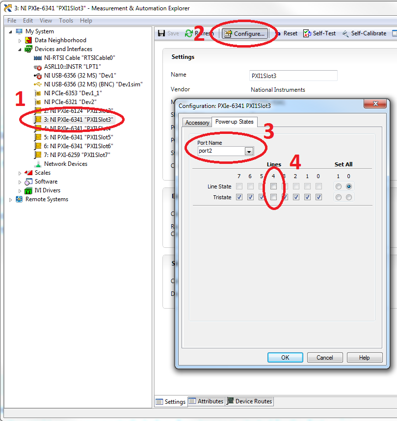
In NI-MAX select the board controlling the shutter and select 'Configure'. PFI12 maps to port2/line4. Deselect the Tristate default output and ensure that the line state checkbox is unchecked (output = low)
Example
This example illustrates how to configure two shutters and assign them to the defined scanning systems: ResScanner and LinScanner.
Shutter 1 is configured to be opened for imaging with ResScanner and both shutters 1 and 2 are opened for imaging with LinScanner.
If Shutters are configured after the initial ScanImage or new Machine Data File setup, the ScanImage Machine Configuration editor can be accessed by selecting the Machine Configuration... option in the File Menu on the Main Controls panel.
Select the Shutter Configuration section in the ScanImage Machine Configuration Editor.

Enter a Shutter Name and select the associated DAQ device, Channel ID and Shutter Open Digital Level for each shutter you want to configure, and save.
Select either High or Low to indicate the TTL level corresponding to the open state for the Shutter line.
Enter a Shutter Transition Time, in seconds. This value is applied to all defined shutters.
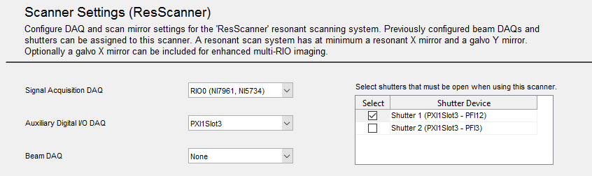
Select the Scanner Settings section for the "ResScanner" resonant scanner in the ScanImage Machine Configuration Editor.
For this example, select Shutter 1 within the Shutters table on the page and save.
Select the Scanner Settings section for the "LinScanner" resonant scanner in the ScanImage Machine Configuration Editor.
For this example, select both Shutter 1 and Shutter 2 within the Shutters table on the page and save.
