Channel Configuration
To configure output channels, open the Machine Configuration Editor section 'Closed-Loop Experiment Outputs'. Each output channel can be of one of the following types:
| Daq Name | Channel ID | Description | |
|---|---|---|---|
| Software | None | None | Does not generate an output, just calls the user defined output function |
| Analog Output | <DAQ Name> | AOx | Outputs an analog signal on the specified analog output |
| Digital Output | <DAQ Name> | PFIx | Outputs a digital signal on the specified PFI channel |
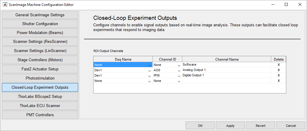 Configuration of three output channels: (1) Software (2) Analog Output (3) Digital Output; The Channel Name can be chosen arbitrarily.
Output Configuration
Each output channel can be configured to process the the value of multiple integration ROIs. In the Integration Controls, select the ROIs to be passed to the output function.
The output function needs to accept the following inputs:
| input name | description |
|---|---|
| vals | 1xN array of integration values of the selected ROIs |
| varargin | advanced parameters |
The output function needs to generate the follwing outputs:
| Function output | Description | |
|---|---|---|
| Software Channel | Empty array [] | Any output by the function is ignored |
| Analog Channel | Numeric scalar within range -10..10 | Voltage level to drive the analog output |
| Digital Channel | Logical scalar | Logic level to drive the digital output |
The physical channels are only updated when the output value changes (i.e. if the function generates the same output multiple times, the physical channel is only update once).
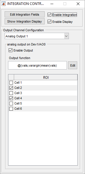
The output channel 'Analog Output 1' is configured to output the average of Cell2 and Cell 3.
User defined output function
Instead of the default anonymous function, ScanImage can call a function defined in a .m file on the path. To call a function, replace the anonymous function call as follows:
@(varargin)myOutputFunction(varargin{:})
The user defined output function can be used to perform a variety of tasks. The following example averages all passed integration values and
function outputVal = myOutputFunction(vals,varargin)
  persistent hLine
  persistent history
  persistent historyPointer
  historyLength = 100;

  if isempty(hLine) || ~isvalid(hLine)
    hFig = figure();
    hAx = axes('Parent',hFig,'XLim',[1,historyLength]);
    hLine = line('Parent',hAx,'XData',NaN,'YData',NaN,'Color','b');
  end

  if isempty(history) || length(history) ~= historyLength
    history = nan(1,historyLength);
  end

  if isempty(historyPointer) || historyPointer > historyLength
    historyPointer = 1;
  end

  outputVal = mean(vals); % calculate the output value by averaging all input values
  history(historyPointer) = outputVal;
  historyPointer = historyPointer + 1;
  if historyPointer > historyLength
    historyPointer = 1;
  end

  history(historyPointer) = NaN;

  hLine.XData = 1:historyLength;
  hLine.YData = history;
end
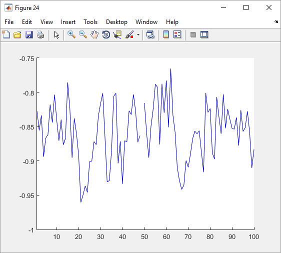
Plot generated by myOutputFunction