Introduction
Low rep rate (<10 MHz) lasers are common for applications such as 3-photon imaging. Capturing the fluorescence signal produced by such a laser requires important considerations. In a normal imaging regime, each pixel represents the mean fluorescence signal integrated over the dwell time of that pixel. When using a low rep rate laser, the signal consists of long empty periods between the laser pulses, consisting of only noise and zero useful signal. Including these empty periods in the integration will significantly reduce signal-to-noise ratio (SNR). New in ScanImage 2018a is the ability to apply a sampling window with respect to the laser pulse, allowing the empty region between laser pulses to be ignored. This increases SNR by omitting the unnecessary noise regions from the data analysis. This feature can be used in both resonant and linear scan modes.
Setting Up a Low Rep Rate Laser
The first step to using this feature is to set up the hardware. This involves wiring the laser clock output from the laser to the DAQ equipment. For resonant scanning, this requires the NI SCB-19 digital breakout plugged into the front of the digitizer. The laser clock signal should be wired into any of DIO0.0-DIO0.3. For linear scanning the clock can be connected to any PFI line of the Auxiliary Digital I/O DAQ.
Once the laser clock is selected, the settings in the Machine Data File must be updated accordingly. Launch the Machine Configuration Editor by launching ScanImage and clocking modify on the startup window. Go to the Scanner Settings page and click the "Advanced" button at the bottom. A setting for specifying the laser clock port will appear. Indicate the port where you connected the laser clock.
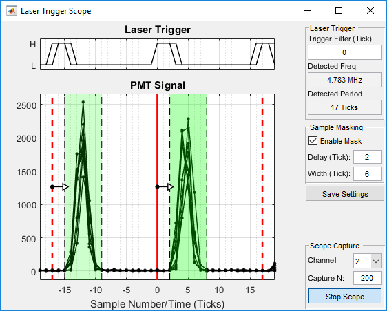
At this point you are ready to start scanning. Launch ScanImage and start imaging a sample. To configure the sampling window, open the Laser Trigger Scope from the view menu on the MAIN CONTROLS GUI. This tool will allow you to see the PMT signal response to laser pulses in real-time. To get started, click "Start Scope". You should now see live updating signal traces. The "Detected Frequency" indicator should show the correct laser frequency. If you do not see any live data and/or the frequency is missing or wrong, verify wiring and the correct Machine Data File setting. If jitter is observed in the Laser Trigger trace, try increasing the Trigger Filter value.
To enable the sample masking, check the "enable mask" checkbox. Drag the green window to specify what samples should be included in pixel integration. Drag the edges to change the width of the window. If you are actively imaging, you should see the effect of the settings in the channel window in real-time. Once you are happy with your settings, click the "Save Settings" button. The settings are saved to the machine data file.