- Overview
- General ScanImage Settings
- Shutter Configuration
- Power Modulation (Beams)
- Scanner Settings - Resonant Scanner
- Scanner Settings - Linear Scanner
- FastZ Actuator Setup
- Photostimulation
- Closed-Loop Experiment Outputs
- ThorLabs BScope2 Setup
- ThorLabs ECU Scanner
- PMT Controllers
- Analog Stage Controller
Overview
The ScanImage Machine Configuration Editor is a graphical user interface used to configure the settings of microscope hardware to be used in the ScanImage application.
Only sections that are always required and sections that are dependent upon the entry and existence of certain information are available. For instance,the PMT Controllers section would not be available for setting entry unless the "Analog PMT Controller" option is selected as an additional component in the General ScanImage Settings section.
After ScanImage has been installed, when the ScanImage Machine Configuration Editor is run, four buttons are available on the bottom of each page: OK, Apply; Revert; and Cancel.
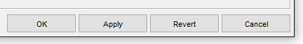
- OK commits all changes made on all settings pages to the Machine Data File (MDF) and closes the ScanImage Machine Configuration Editor.
- Apply commits only those changes made to the current page, to the Machine Data File (MDF) . The ScanImage Machine Configuration Editor remains open for additional data entry.
- Revert changes the data on the current page back to its last applied state (Applied button was pressed) or its original state at the time the ScanImage Machine Configuration Editor was opened (Applied button was not pressed). The ScanImage Machine Configuration Editor remains open for additional data entry.
- Cancel Changes the data on all pages back to its last applied state (Applied button was pressed) or its original state at the time the ScanImage Machine Configuration Editor was opened (Applied button was not pressed) and closes the ScanImage Machine Configuration Editor.
General ScanImage Settings
The General ScanImage Settings section is where you define Scanning systems, select additional components and plugins, and enter additional general setup information for your microscope used within ScanImage.
List all scanning systems to control on this microscope. For each scanning system, specify whether it is a "Resonant" (resonant-galvo scan mirror pair) or a "Linear" (galvo-galvo scan mirror pair).
A separate configuration section will be provided, appropriate for the Scanner Type, for each scanning system defined.

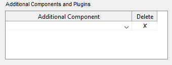
Additional components and plugins can be configured for ScanImage. You can either select one of the available ScanImage components, or enter a custom component.
The components/plugins available for configuration in ScanImage include: ThorLabs BScope2; ThorLabs ECU Scanner; and Analog PMT Controller.
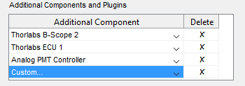
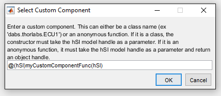
If you have a custom component you would like to configure, select the "Custom..." option. A dialog box pops up prompting you to enter information about the custom component.
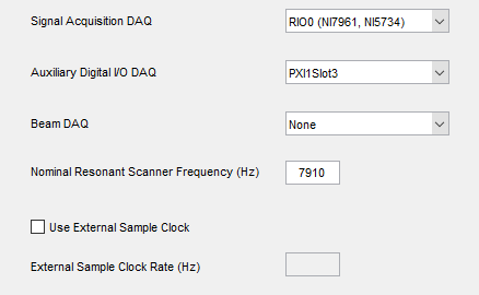
Additional settings options include the entry of a custom startup script, the option to run in a simulated mode an the scan angle resolution.
In the case where you would like some custom initialization software to run follow ScanImage startup, you can enter your startup script.

If you want to test out your settings without running the actual microscope hardware, or if you want to enter your settings before your microscope hardware setup and installation is complete, you can check the "Run in Simulated Mode" option.

To turn simulated mode off, simply bring up the ScanImage Machine Configuration Editor by selecting the Main Controls File Menu, Machine Configuration option, uncheck this option and save your changes.
Shutter Configuration
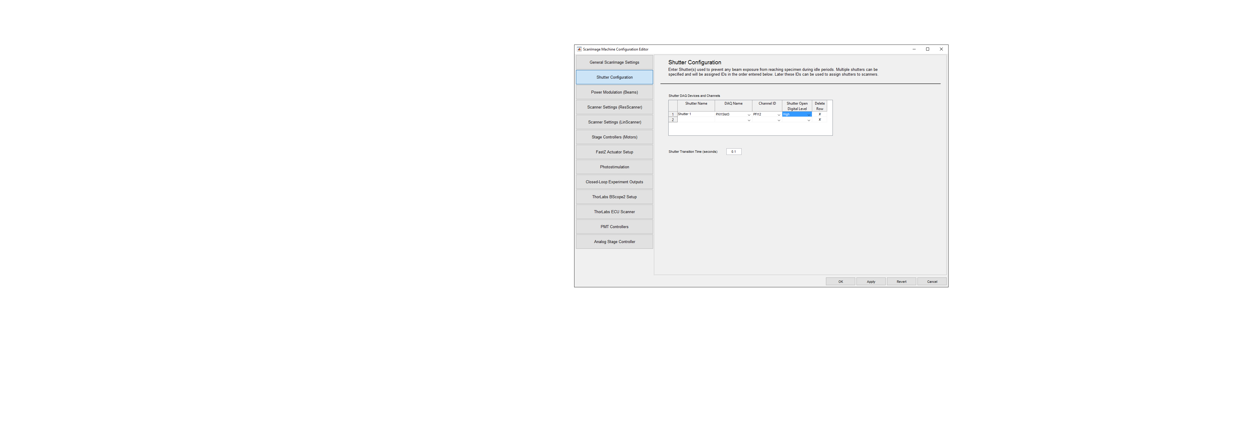
The Shutter Configuration section is where you enter information about Shutters used within ScanImage.
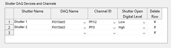
In this section, enter Shutter(s) used to prevent any beam exposure from reaching the specimen during idle periods. Multiple shutters can be specified and will be assigned IDs in the order entered. These IDs can be used to assign shutters to scanners.

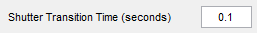
The Shutter transition time, which is the time it takes for the shutter to change state (open to close; or close to open), can be set. A default of 0.1 is provided.
Configuration Tips
DAQ Name
Channel ID
- Shutter Open Digital Level
See Shutter Configuration for guidance on how to set the Shutter Open Digital Level for a shutter.
Power Modulation (Beams)
The power Modulation (Beams) section is where you configure DAQs (data acquisition devices) for beam power modulation. Each scanner can be assigned one beam DAQ. Multiple scanners can be assigned the same beam DAQ, but cannot be used simultaneously.
Select a beam device by choosing a device listed under "Available DAQ Devices" and pressing the ">>" button to move that selection under the "Selected Beam DAQ Devices". This can be undone by selecting the device under the "Selected Beam DAQ Devices" and pressing the "<<" button.
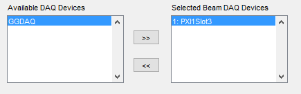
The name of the current selected beam in the "Selected Beam DAQ Devices" list is appended to the Panel title "Beam DAQ " and is the beam whose configuration settings is in focus.

In the Beam DAQ Panel are configuration settings for channel(s), shutter(s) and trigger routings for the selected beam.
To begin, configure a channel for each beam power modulation device (pockels cell, AOM, etc) to be controlled by this beam DAQ. The calibration offset can be measured later.

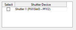
Next, select which shutters (if any) must be opened during the power modulation calibration of this beam DAQ.
All shutters configured in the "Shutter Configuration" section are listed. To select, check the associated check box.
Finally, configure the line clock, frame clock and reference clock trigger routes.

Trigger routing must be set manually for some hardware configurations.
- For Resonant Scanning, automatic routing can be used if beam DAQ is the same PXI chassis as the FPGA/digitizer.
Otherwise, the line clock must be wired (Wiring Guide for Resonant Scanning Beams) and the associated "Line Clock Input Terminal" setting selected. - For Linear Scanning, automatic routing works if the Beam DAQ is in the same PXI chassis as the Auxiliary Clock Device or is connected to that device by the RTSI cable.
Otherwise, the frame clock and the reference clock must be wired (Trigger Wiring Guide for Linear Scanning) and the associated "Frame Clock Input Terminal" and the "Reference Clock Input Terminal" settings selected.
Configuration Tips
DAQ Name
Channel ID
Scanner Settings - Resonant Scanner
Scanners Settings must be applied for each Resonant Scanning system defined in the General ScanImage Settings section. A separate section will be created for each Resonant Scanning system. The section label will contain the name of the scanning system.
In the Resonant Scanning section, you will configure DAQ and scan mirror settings for the Resonant Scanning system. Previously configure beam DAQs and shutters can be assigned to this scanner,
A resonant scanning system has at minimum a resonant X and a galvo Y mirror. An optional galvo X mirror can be included for enhanced multi-ROI (Region of Interest) imaging.
Select which shutters (if any) that must be open when using this scanner.
All shutters configured in the "Shutter Configuration" section are listed. To select, check the associated check box.
Scanner Settings - Linear Scanner
Scanners Settings must be applied for each Linear Scanning system defined in the General ScanImage Settings section. A separate section will be created for each Linear Scanning system. The section label will contain the name of the scanning system.
In the Linear Scanning section, you will configure DAQ and scan mirror settings for the Linear Scanning system. Previously configure beam DAQs and shutters can be assigned to this scanner,
Select which shutters (if any) that must be open when using this scanner.
All shutters configured in the "Shutter Configuration" section are listed. To select, check the associated check box.
FastZ Actuator Setup
Photostimulation
Closed-Loop Experiment Outputs
ThorLabs BScope2 Setup
ThorLabs ECU Scanner
PMT Controllers
Analog Stage Controller