vDAQ Acquisition System
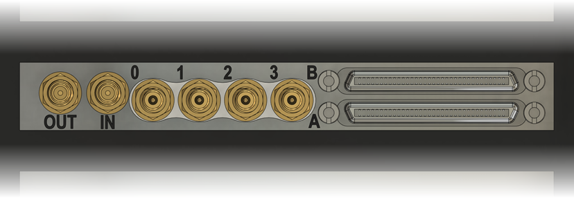
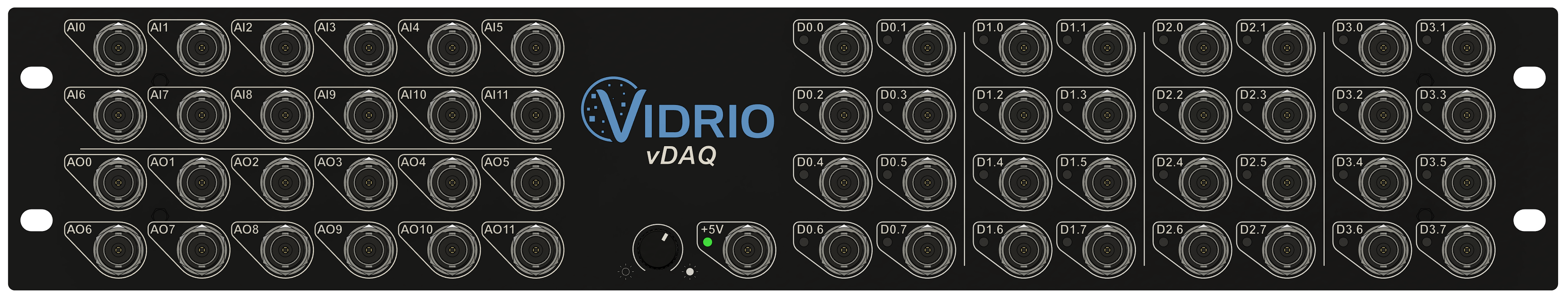
The vDAQ acquisition system consists of the PCIe card installed in the PC and a breakout accessory connected by two cables to the PCIe card. The connector plate of the PCIe card (rear of PC) contains 4 high speed signal inputs for PMT signals and clock input/output terminals. The breakout has an analog input section at the top left with 12 inputs, an analog output section at the bottom left with 12 outputs, and a digital section at the right. The digital section is divided into 4 logical groups with 8 lines in each group.
Rear of PC:
Breakout:

Microscope Wiring
The vDAQ system is flexible in how microscope systems are wired up. Signals can be connected to any channel of the appropriate type. The different types of control signals are listed below based on the appropriate channel type. PMT signals attach directly to the back of the PCIe card using SMB cables.
Analog Outputs
| Signal | Description |
|---|---|
| Galvo Position Control | Each galvo scanner in the system will have a position control signal |
| Resonant Zoom Control | Scan amplitude control for resonant scanners |
| Beam Power Control | Control signal for pockels cells, or AOMs |
| Fast Focus Control | Piezo scanners, remote focus mirror, ETLs |
| PMT Gain Control | Some PMT controllers accept an analog signal to control the PMT gain |
Analog Inputs
| Signal | Description |
|---|---|
| Galvo Position Feedback | Some galvo controllers provide a feedback signal to measure the galvo position in real-time |
| Beam Power Feedback | Beam power signal, typically supplied from a photodiode measuring from a beam pick-off |
| Fast Focus Feedback | Some fast focus devices (such as piezos) provide a feedback signal to measure position in real-time |
Digital Inputs
Digital inputs can be connected to any line in digital groups 0, 1 and 2.
| Signal | Description |
|---|---|
| Resonant Sync (Period Trigger) | Provided by resonant mirror driver as critical synchronization signal used for image formation. |
| Start Trigger | A TTL transition will cause a running Acquisition Mode to start it's first Acquisition. |
| Next File Trigger | A TTL transition will cause a LOOP to start the next Acquisition. |
| Stop Trigger | A TTL transition will cause a running Acquisition to end. |
| PMT Trip Status | Some PMT controllers provide a TTL signal to indicate a "tripped" condition |
| Aux Triggers | Digital inputs to timestamp |
| I2C Clock/Data | Clock (SCL) and data (SDA) lines for recording I2C messages (note, SDA must be wired to group 0 or 1 in order for "ack" output to be enabled) |
Digital Outputs
Digital inputs can be connected to any line in digital groups 0, 1 and 3.
| Signal | Description |
|---|---|
| Resonant Scanner Enable | Some resonant scan systems accept a TTL signal to enable the resonant scanner |
| Shutter Control | Some shutters accept a TTL to control shutter position |
| PMT Power Control | Some PMT Controllers accept a TTL signal to activate the PMT |
| PMT Trip Reset | Some PMT Controllers accept a TTL signal to clear a "tripped" condition |
| Imaging Clock Signals | ScanImage can output various clock signals which can be useful for synchronizing other equipment to imaging. Available clock signals include: Pixel clock, line clock, beam clock, frame clock, and volume clock |
Example Wiring Configuration
The table below lists signal connections for a dual-path microscope with one RGG scan path with remote focus, one GG scan path with ETL, one pockels cell on each path, and one shutter on each path
| Signal | Channel |
|---|---|
| Scanner 1 X Galvo Control | AO0 |
| Scanner 1 Y Galvo Control | AO1 |
| Scanner 1 X Galvo Feedback | AI0 |
| Scanner 1 Y Galvo Feedback | AI1 |
| Scanner 1 Resonant Zoom Control | AO2 |
| Scanner 1 Resonant Enable Control | D3.0 |
| Scanner 1 Resonant Sync | D2.0 |
| Scanner 1 Pockels Control | AO3 |
| Scanner 1 Calibration Photodiode | AI3 |
| Scanner 1 Remote Focus Control | AO4 |
| Scanner 1 Remote Focus Feedback | AI4 |
| Scanner 1 Shutter | D3.1 |
| Scanner 2 X Galvo Control | AO5 |
| Scanner 2 Y Galvo Control | AO6 |
| Scanner 2 X Galvo Feedback | AI5 |
| Scanner 2 Y Galvo Feedback | AI6 |
| Scanner 2 Pockels Control | AO7 |
| Scanner 2 Calibration Photodiode | AI7 |
| Scanner 2 ETL Control | AO8 |
| Scanner 2 Shutter | D3.2 |