Introduction
I2C is a simple two wire serial bus. To synchronize a behavioral experiment with imaging, ScanImage can act as a I2C bus slave. When an event occurs, the controller of the behavioral experiment can send data bytes to ScanImage. ScanImage will timestamp the incoming packet and log the data bytes to the Tiff header of the appropriate image frame. To learn more about the I2C protocol, review the I2C Wikipedia article.
Wiring
The I2C bus is directly monitored by the ScanImage FPGA. The I2C bus requires both the Serial Data Line (SDA) and Serial Clock Line (SCL) to be pulled to VDD. For this purpose, +5V output on the breakout can serve as VDD. To calculate a resistance value for the pull-up resistors, please review this resource.
| Bus line | vDAQ Channel | SCB-19 Pin |
|---|---|---|
| SDA | Any channel in group 0, 1, or 2* | PFI0 |
| SCL | Any channel in group 0, 1, or 2 | PFI1 |
| VDD (optional) | +5V | +5V |
*When "ack" output is enabled (see below) SDA must be in digital group 0 or 1
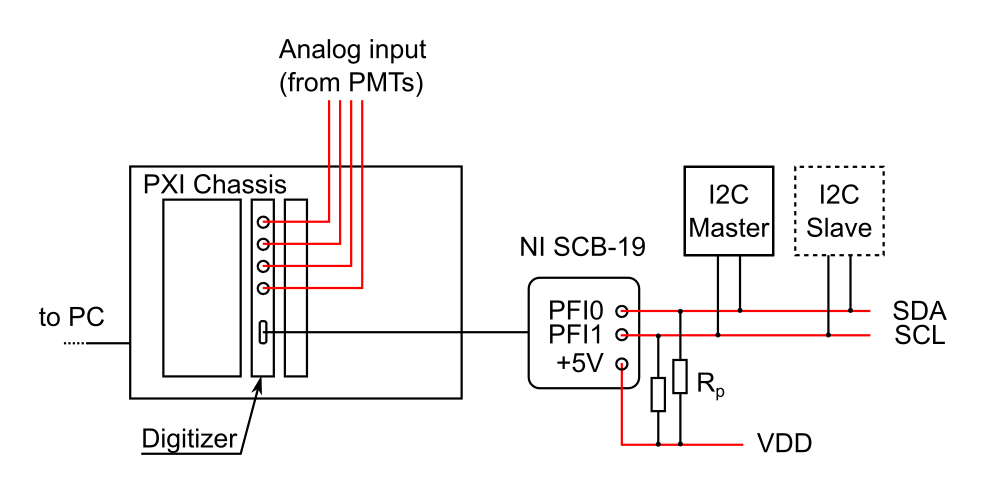
Sample wiring diagram for ScanImage as I2C slave. SDA and SCL are pulled to VDD via pull up resistors Rp.
Software
To configure ScanImage as an I2C slave, add the following lines to the 'ResScan' section of the Machine Data File:
%% ResScan

...

% auxTriggering, photonCouting and I2C are mutually exclusive features
auxTriggersEnable = false;	     % disable auxTriggersEnable so that I2C can be used
photonCountingEnable = false;    % disable photonCountingEnable so that I2C can be used

I2CEnable = true                 % enable I2C slave capability of FPGA
I2CAddress = uint8(0);   		 % [byte, 0-127] configures the I2C address of the FPGA
I2CDebounce = 500e-9;   		 % [s] time the I2C signal has to be stable before a change is registered
I2CStoreAsChar = false; 	     % if false, the I2C packet bytes are stored as a uint8 array. if true, the I2C packet bytes are stored as a string. Note: a Null byte in the packet terminates the string
I2CDisableAckOutput = false;     % the FPGA confirms each packet with an ACK bit by actively pulling down the SDA line. I2CDisableAckOutput = true disables the FPGA output
I2C packet format
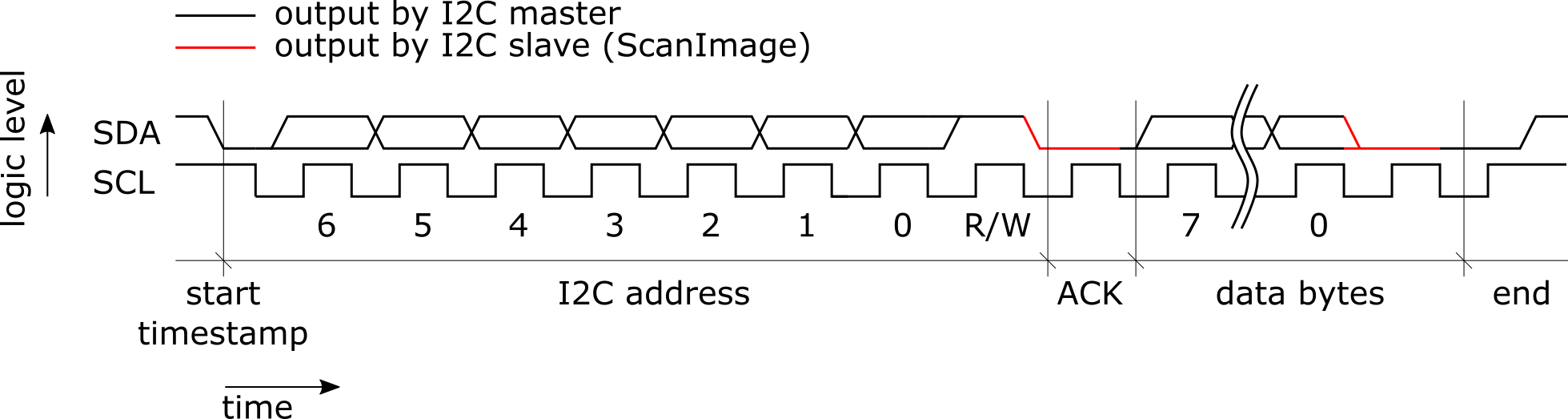
Sample of an I2C data package sent by the I2C master to an I2C slave. The transmission starts when the master pulls SDA to low while SCL is high. The master generates the clock and the ScanImage FPGA samples SDA on the rising edge of SCL. SDA needs to remain at a stable logic level for the entire duration of SCL high. The first byte sent by the master is the address of the slave. The following bytes are data bytes. The slave confirms receiving the byte by pulling SDA to low after the last bit in the byte. At the end of the transmission or if the transmission fails, the master releases SDA while SCL is high.
Data format
ScanImage saves received packets in the Tiff header of the appropriate image frame. When a start of packet signal is registered on the I2C bus, the FPGA generates a high precision time stamp which is saved with the data to the frame header. Depending on the Machine Data File setting 'I2CStoreAsChar' ScanImage stores the packet either as 'binary' byte array (each byte is a value of 0-255) or as string. If saved as a string, a received byte of value 0 is interpreted as the end of string.
I2C = {{timestampPacket1, [byte1 byte2 ... byteN ]} ... {timestampPacketN, [byte1 byte2 ... byteN ]}}
I2C = {{timestampPacket1, 'my data 1'} ... {timestampPacketN, 'my data 2'}}
Emulate I2C master using a NI-DAQ board
A Matlab example using an NI-DAQ board as an I2C master can be downloaded here.