Steps to integrate a Thorlabs ECU1 or ECU2 (BScope 2) into a ScanImage 2016 system:
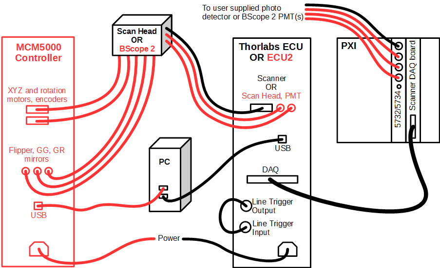
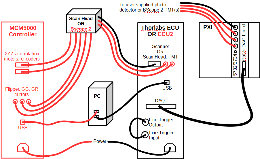
Wire the Thor ECU and ScanImage 2016 system
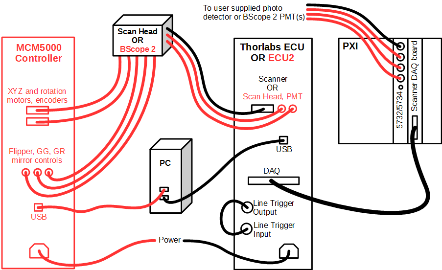
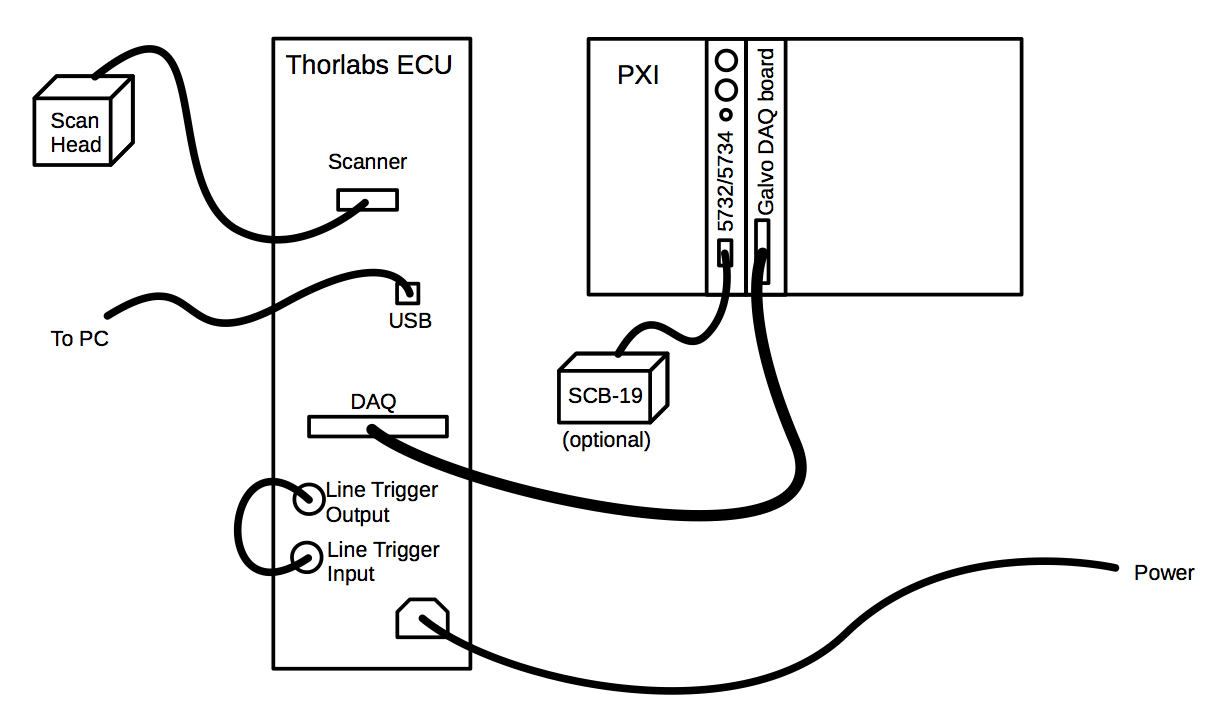
Use the image below as a guide. Items in black apply to both ECU1 and ECU2/BScope 2 while items in red apply only to the ECU2/BScope 2.
- Loop the ECU's line clock output terminal back to the ECU's line clock input terminal
- Connect the Thor ECU to the scanner system
- For ECU1, connect the single DVI connector to the resonant/galvo scanner assembly
- For ECU2/BScope 2, connect all cables for PMT and scanner controls. There will be a 25 pin D-sub for each of the two parallel scan paths and two round cables for each PMT
- If using a BScope 2, connect the MCM5000 controller. For each stage axis (X, Y, fine Z, coarse Z, rotation) there will be two D-sub cables, one for the motor and one for the encoder. There will also be three round mirror control cables
- Connect the 68pin DAQ connector to the scanner control DAQ board of the ScanImage 2016 system
- Connect the ECU's USB cable to the ScanImage 2016 PC. Windows will automatically download the drivers (requires an Internet connection) and register a USB serial port.
- If using a BScope 2, also connect the USB cable to the MCM5000 controller. An unknown device should appear in the device manager.
- Use device manager to update the device driver and choose the option to manually select driver location.
- Locate the BScope_ControlV3 driver package from Thorlabs.
- After installing, a second USB serial port should appear in the device manager.
Start ScanImage
Start ScanImage 2016 and select the option to create a new machine data file.
Configure ScanImage
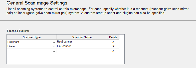
The ScanImage Machine Configuration Editor will be started. Beginning with the General ScanImage Settings section, enter settings information appropriately.
As sections are configured, modify them appropriately then press Next. When the Additional Components section is reached, you can press Finish or Finish and Run ScanImage to save configured information to the given machine data file.
Machine configuration can be updated at a later time by selecting the Machine Configuration... option on the File Menu on the Main Controls panel.
Integrate ThorLabs ECU and/or BScope 2 into ScanImage
To configure ThorLabs ECU and/or BScope 2, they must first be added within the ScanImage Machine Configuration Editor.
In the General ScanImage Settings section, add "Thorlabs ECU 1" and/or "Thorlabs B-Scope 2" to the Additional Components and PlugIns table, depending on your hardware.
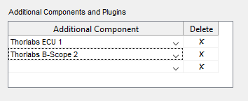
The ScanImage Machine Configuration Editor will add settings sections, accordingl
A Thorlabs ECU Scanner Settings section is added if "Thorlabs ECU 1" is selected as an additional component; and a ThorLabs BScope2 Setup section is added if "Thorlabs B-Scope 2" is selected as an additional component.
Configure Thorlabs ECU Scanner
Select the ThorLabs ECU Scanner section In the ScanImage Machine Configuration Editor.
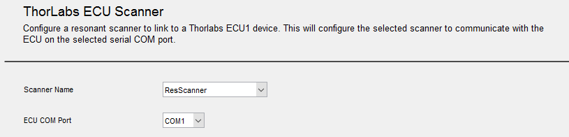
Select the resonant scanning system you defined in the General ScanImage Settings section. Only scanners that have a "Resonant" Scanner Type are available in the Scanner Name dropdown list.
Recap:
Select the ECU COM Port of USB to serial adapter that installs when USB cord was plugged in. Use the device manager to determine this.
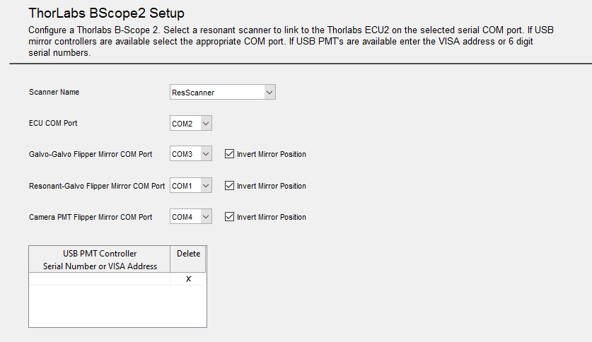
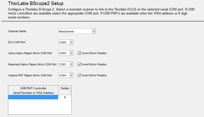
Configure Thorlabs B-Scope 2
Select the ThorLabs BScope2 Setup section In the ScanImage Machine Configuration Editor.
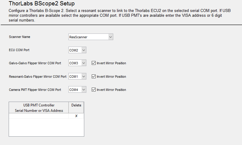
Select the resonant scanning system you defined in the General ScanImage Settings section. Only scanners that have a "Resonant" Scanner Type are available in the Scanner Name dropdown list.
Recap:
Select the appropriate COM Ports for ECU, Galvo-Galvo Flipper mirror, Resonant-Galvo Flipper mirror, and Camera PMT Flipper mirror.
See ThorLabs BScope2 Settings for additional setup information.

Configure Resonant Scanning System
Select the Scanner Settings section for the defined Resonant scanning system, In the ScanImage Machine Configuration Editor. The defined scanning system will appear in the section name.
Enter the additional Resonant and Galvo mirror configuration.
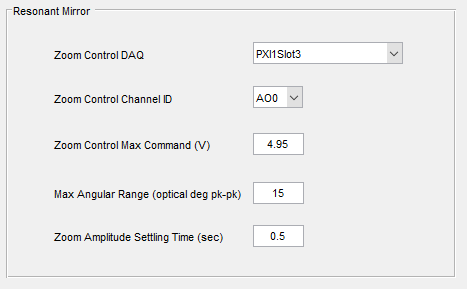
Resonant Mirror settings
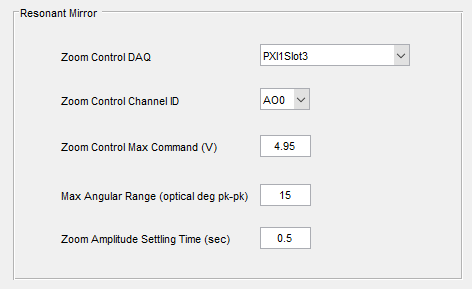
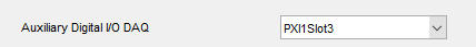
Select the name of the DAQ device where Thorlabs ECU is plugged in (found in NI MAX. (ex: 'PXI1Slot3')) in the Zoom Control DAQ.
Defaults are provided by the system. Change default entries as needed.
Galvo Mirror settings

Defaults are provided by the system. Change default entries as needed.