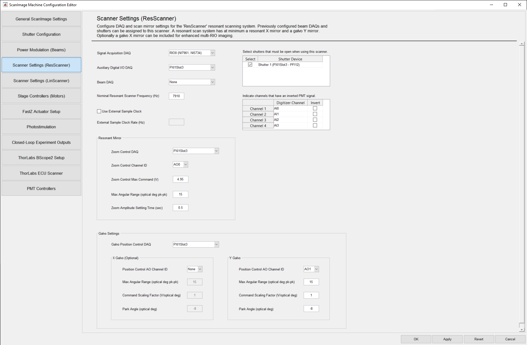
Resonant Scanning Settings Panel
ScanImage creates a separate settings page for each Resonant Scanner configured on the General ScanImage Settings page.
The defined Resonant Scanner name will appear next to the Scanning Settings label in the page name.
In the display above, a resonant scanner called "ResScanner" was defined as the name associated with a Resonant Scanning System on the General ScanImage Settings page.
Top Panel Display Settings
| Signal Acquisition Daq | FlexRIO Device as specified in MAX. The default is set to to "RIO0". |
| Auxiliary Digital IO Daq | Select a DAQ where the digital signals will be wired. Digital signals can include:
|
| Beam Daq | Select the Beam DAQ to use with the resonant scan system. All beams configured on the Power Modulation (Beams) page will be available in this list. |
| Nominal Resonant Scanner Frequency (Hz) | Enter the nominal frequency, in Hz, of the resonant scanner. A default of 7910 is provided. |
| Use External Sample Clock | Check the Use External Sample Clock checkbox if the external sample clock is connected to the CLK IN terminal of the FlexRIO digitizer module. The default is unchecked. |
| External Sample Clock Rate (Hz) | Enter the nominal frequency, in Hz, of the external sample clock onnected to the CLK IN terminal (e.g. 80e6). The actual rate is measured on the FPGA. |
| Shutter Device | This is a read-only field that displays the name of a Shutter configured on the Shutter Configuration Settings page. |
| Select | Check the Select Checkbox for those Shutters you want associated with the Selected Beam Daq Device. The default is unchecked. |
| PMT Channel Name | This is a read-only field that displays the system generated Channel Name. |
| Digitizer Channel | This is a read-only field that displays the Digitizer Channel associated with the PMT Channel Name. |
| Invert | Select the Invert checkbox if the input signal for that Channel is inverted (e.g. more negative for increased light signal). The default is unchecked. |
- All Digitizer Channels are displayed in the Channels Table.
- All shutters that have been configured on the Shutter Configuration Settings page and saved will appear in the Shutters table.
- To select a shutter(s) for a beam, check the Select checkbox next to the desired Shutter Device.
Resonant Mirror Settings
| Zoom Control Daq | Select the NI-DAQ board to host the resonant zoom analog output. |
| Zoom Control Channel ID | Select the Analog Output channel to be used to control the Resonant Scanner Zoom level. The default is AO0. |
| Zoom Control Max Command (V) | Enter the voltage level that drives the Resonant Mirror to maximum amplitude.
|
| Max Angular Range (optical deg pk-pk) | Enter the maximum range value in optical degrees (pk-pk) for the resonant mirror. A default of 15 is provided. |
| Zoom Amplitude Setting Time (sec) | Enter the time, in seconds, to wait for the resonant scanner to reach its desired frequency after an update of the zoomFactor. A default of 0.5 is provided. |
Galvo Mirror Settings
| Galvo Position Control Daq | Select the NI-DAQ board to be used to control the Galvo(s). The name of the DAQ-Device can be seen in NI MAX (e.g. 'Dev1' or 'PXI1Slot3'). The selected DAQ board needs to be installed in the same PXI chassis as the FPGA board. |
| X Galvo Position Control AO Channel ID | Select the Analog Output channel to be used to control the X Galvo. 'None' can be selected for standard Resonant Galvo scanners. |
| X Galvo Max Angular Range (optical deg pk-pk) | Enter the maximum range in optical degrees (pk-pk) for the X Galvo, if present. If present, a default of 15 is provided. |
| X Galvo Command Scaling Factor (V/optical deg) | Enter the Galvo conversion factor from optical degrees to volts, for the X Galvo, if present. Negative values invert scan direction. If present, a default of 1 is provided. |
| X Galvo Park Angle (optical deg) | Enter the Optical degrees from center position for the X Galvo to park at when scanning is inactive. if present, a default of -8 is provided. |
| Y Galvo Position Control AO Channel ID | Select the Analog Output channel to be used to control the Y Galvo. The default is AO1. |
| Y Galvo Max Angular Range (optical deg pk-pk) | Enter the maximum range in optical degrees (pk-pk) for the Y Galvo. A default of 15 is provided. |
| Y Galvo Command Scaling Factor (V/optical deg) | Enter the Galvo conversion factor from optical degrees to volts, for the Y Galvo. A default of 1 is provided. Negative values invert scan direction. |
| Y Galvo Park Angle (optical deg) | Enter the Optical degrees from center position for the Y Galvo to park at when scanning is inactive. A default of -8 is provided. |
- X Galvo "Present" refers to an X Galvo whose Position Control AO Channel ID that is not "None".