Introduction
Each ScanImage scanner (ResScan / LinScan) uses its own normalized coordinate system to allow for different field of views. The scanner coordinates are mapped into a common reference space. The reference space is used in the ScanImage API and all GUIs exposed to the user.
This article gives an overview about the ScanImage terminology and
Scanner Coordinates
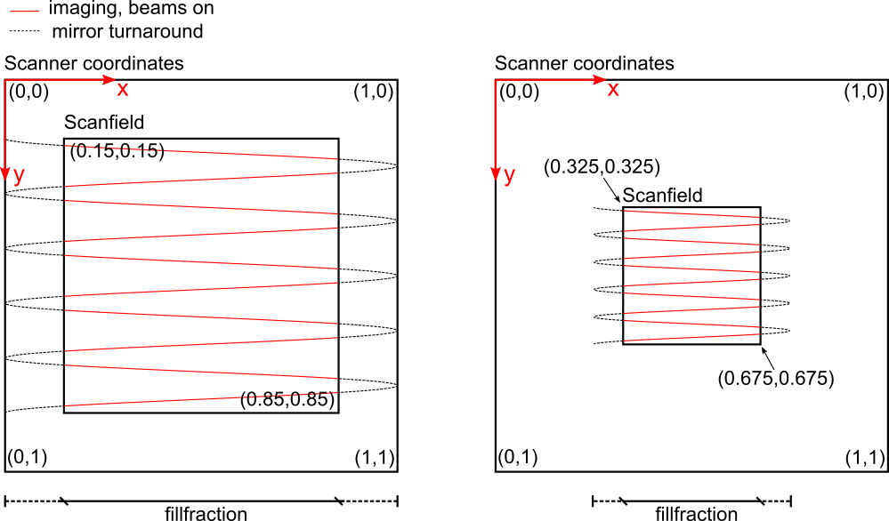
The scanner coordinates are a normalized coordinate system with x and y extending from 0 to 1. This extent is regardless of the size and the aspect ratio of the actual scanner field of view and defines the maximum addressable space of the scanner.

A scanfield defined in scanner coordinates.
Left: Zoom 1x, spatial fillfraction 0.7
Right: Zoom 2x, spatial fillfraction 0.7
Reference Coordinates
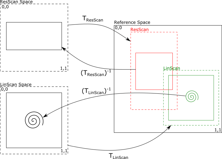
The scanner spaces are mapped into a common reference space via affine transformations. All Scanfields and stimuli are defined in reference space and then mapped back into the appropriate scanner space to control the scanner hardware. The aspect ratios in reference space show the true proportions of the scanners in the system.
To simplify the alignment of the scanners relative to each other, ScanImage features an Alignment GUI. After a successful alignment, ScanImage stores the affine matrices used for the transformation as properties in the imaging system objects:
hSI.hResScan.scannerToRefTransform % affine transformation for ResScan
hSI.hLinScan.scannerToRefTransform % affine transformation for ResScan

Example for mapping Scanner coordinates to Reference Space
ResScan: Note that the angular range of the y-galvo is twice the angular range of the resonant scanner in this example. The aspect ratio in Reference Space displays the proportions correctly. The scanfield in ResScan space appears distorted because of the normalized scanner coordinates, but simplifies the algorithms used for hardware control.