Introduction
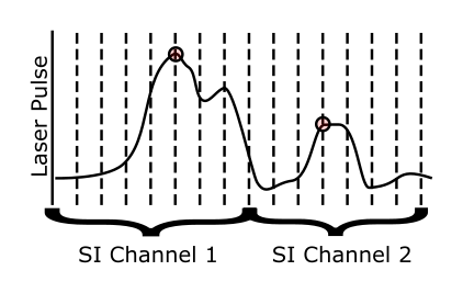
ScanImage 2018 includes a new photon counting module, which uses a fast digitizer (>1GHz) to directly sample the output of the transimpedance amplifier. ScanImage analyzes the voltage signal and performs a peak detection on the signal to count photons in real time. By synchronizing the fast digitizer to the sample clock, time correlated photon counting is supported. This allows ScanImage to bin detected photons into virtual output channels depending on their arrival time.
The fast digitizer can be operated in photo current integration mode, while the photon counting is active. This allows to display the photo current integration signal and compare the photon counted signal at the same time to get a direct comparison between the two modes.
See Photon Counting Controls for more information on the graphical user interface.
Hardware requirements
The following hardware is required to use ScanImage's photon counting software module:
- National Instruments NI5771 fast digitizer and an NI PXIe-7975 FPGA module
- A fast transimpedance amplifier (bandwidth >80MHz) (such as the Femto DHPCA-100)
- (optional) For time correlated photon counting, a clock multiplier board such as the AD9516-0 is required
Configuration
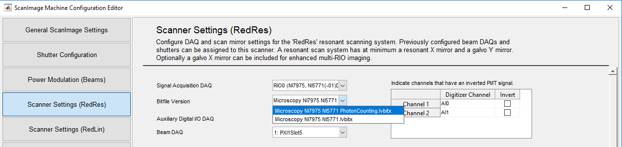
Select the NI7975 and NI5771 digitizer as Acquisition device on the Resonant Scanner Configuration Page. From the dropdown menu, select the bitfile 'Microscopy NI7975 NI5771 PhotonCounting.lvbitx' to enable Photon Counting support in ScanImage.

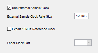
To synchronize the digitizer to the Laser Clock, set up and configure the clock generator, and connect the up-multiplied laser clock to the CLK IN terminal on the NI5771 front panel. In the Resonant Scanner Configuration Page, select 'Advanced Configuration', enable the checkbox 'Use External Sample Clock' and enter the sample clock value in Hz. Note: the value needs to be smaller than or equal to 1.5GHz.
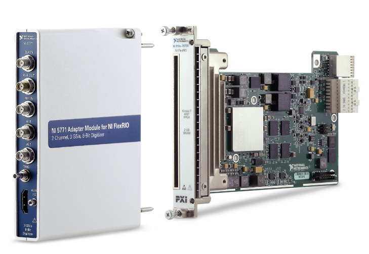
The ScanImage Photon Counting Module requires an NI5771 fast digitizer, and an NI PXIe-7975 FPGA module. The digitizer has 2 analog input channels (8bit) and a maximum sample rate of 1.5GHz.
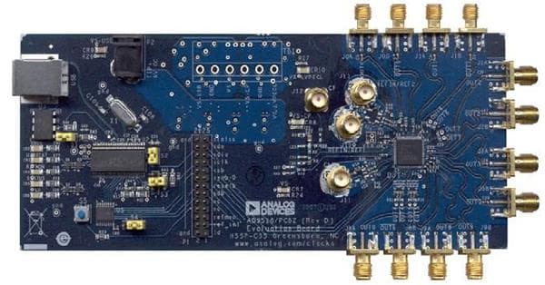
For time correlated single photon counting, a clock generator, such as the AD9516-0, is required to up-multiply the laser clock.
Principle of Operation
For each of the two physical input channels, ScanImage implements two processing pipelines: A photon integration pipeline, and a photon counting pipeline. The output of these pipelines can be mapped to ScanImage channels by the user such that the same sample can be recorded both in photo current integration mode and in photon counting mode at the same time.
The photon counting pipeline implements the following stages:
| Pipeline stage | Photo Current Integration | Photon Counting | |
|---|---|---|---|
| 1 | Offset subtraction and scaler | x | x |
| 2 | Centered differentiation filter | x | |
| 3 | Programmable FIR filter | x | |
| 4 | Programmable Photon Discriminator | x |
The offset subtraction and scaler applies to the photon integration pipeline and the photon counting pipeline. The remaining stages apply to the photon counting pipeline only. The centered differentiation filter can be used to remove low frequency noise from the signal. The programmable FIR filter can be used to remove high frequency noise from the signal. The photon discriminator uses a sliding window and a debounce filter to discriminate photons (see figure).

The photon discriminator flags a photon when a sample is is 1) greater than a user settable threshold and 2) the largest signal value within a sliding window (A). If multiple samples within the window have the same signal value because of noise or a flat peak, multiple photons are flagged for a single peak. A debouncing filter checks for each detected photon if it is preceded by another photon within the debouncing time (B). Photons are then counted and binned into pixels (C).
The threshold, the size of the sliding window and the debouncing time are user settable.