Overview
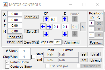
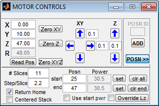
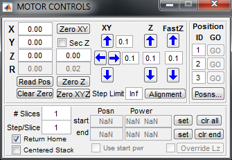
The MOTOR CONTROLS window pertains to (optional) control of a stage/motor controller system supported by ScanImage.
The Motor Controls panel only appears if a motorControllerType is specified in the Machine Data File. Other motorXXX settings in the Machine Data File pertain to this controller, if specified - e.g. the COM port controller is connected to if it is serial-port controlled.
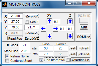
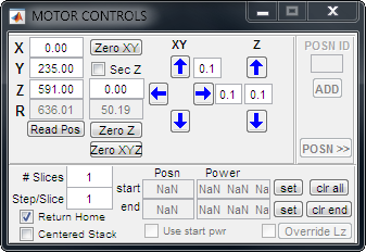
A Secondary Z motor can be activated in the Machine Data File (by specifying the motor2ControllerType). For example, when the primary motor controller is configured with the default value: motorDimensions='XYZ', adding a Secondary Z motor corresponds to the XYZ-Z configuration as shown below. Other configurations, such as XY, Z, XYZ, and XY-Z show 3 dimensions; inactive dimensions are set to zero.
Current Motor Position
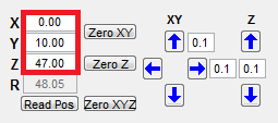 | These controls play two roles:
|
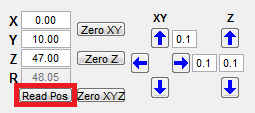 | Forces ScanImage to read the current motor position in all three axes and to update the displayed X/Y/Z values, e.g. following manual adjustment of the motor position using the motor controller outside of ScanImage control. |
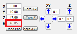 | Read-only control that displays the squared-sum of the 3-4 displayed X/Y/Z values |
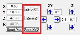 | Pressing these buttons forces ScanImage Relative positions to be used in the specified axes (if not used already) and resets the relative origin in the specified axes to the current position (which is first read from the motor controller).
|
|
|
| Increment or decrement stage position in X, Y, or Z dimension by the specified step, in microns. In 4-dimension XYZ-Z case, the Sec Z value determines which motor controller is used when incrementing/decrementing the Z position. |
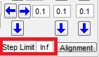 | Defines the maximum step (in motor coordinates) that ScanImage can perform on each axis. Attempting to execute a bigger step results in an error. |
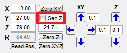
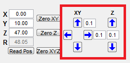
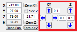
Image Stack Acquisition
These controls configure Image Stack acquisitions, of which ScanImage supports two types:
- Standard ('Slow Z') stepping stacks
- Volume Imaging ('Fast Z') stacks (when Enable is selected in the Fast Z Controls)
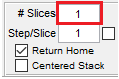
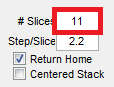
When value of #Slices is greater than 1, an image stack acquisition is implied for each GRAB or LOOP Repeat. For standard stacks, each Slice is an individually triggered acquisition taken at a distinct axial (Z) position, consisting of one or more Frames, as specified by #Frames on the Main Controls window. See Volume Imaging for more information about FastZ stacks.
Core Image Stack Controls
 |
|
 |
|
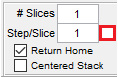
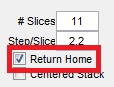
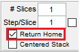 | If enabled, motor controller returns to Home position – the initial axial position when a GRAB or LOOP was initiated – following the GRAB acquisition or each LOOP Repeat. This ensures subsequent acquisitions or Repeats traverse the same axial positions. |
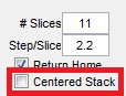
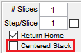 | If enabled, axial position at start of Image Stack acquisition is taken as the center of the stack. Motor is moved backwards by half the total span implied by #Slices and Step/Slice prior to the start of the stack acquisition. |
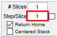
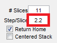
 | Locks the step/slice step size during auto-calculations. Users can set the start and end position of a stack and ScanImage will auto calculate the # of slices and the step per slice needed to achieve this. Because scanning partial slice is not practical this auto-calculation will find the nearest whole number of slices that will accommodate the stack start and end position. However users may decide that the step size is of a greater priority. Enabling this will lock the step per slice value an instead adjust the # of slices so that the entire stack can imaged with the specified step size. This will necessarily mean that the total stack will exceed the limits of the stack determined by the stack start and end. |
Image Stack Endpoint & Power Controls
Often, users may wish to select the starting and ending axial positions, as well as the imaging power, interactively, i.e. during FOCUS when the axial position and power can each be adjusted during live imaging.
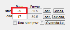 | Sets the starting axial position of stack interactively. Motor controller will be moved to specified axial position at start of subsequent (standard) Image Stack acquisitions. |
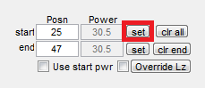 | Sets the current axial position as Posn start. |
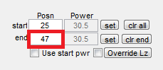 | Sets the ending axial position of stack interactively. When both Posn start and Posn end are set, the values of #Slices and Step/Slice are constrained so that Image Stacks traverse the specified axial extent. |
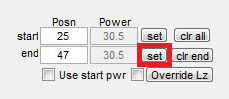 | Sets the current axial position as Posn end. |
 | Clears Posn start, Posn end, Power start, and Power end (if configured.) |
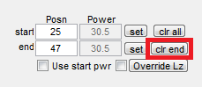 | Clears Posn end and Power end (if configured) only. |
P/Z Adjust
If P/z Adjust is enabled for a particular Beam on the Power Controls window, the following controls pertain:
 | Power to use at starting axial position of stack can be set interactively. If Use start pwr is enabled, then power is adjusted to this level (for selected/displayed Beam) at start of subsequent (standard) Image Stack acquisitions. |
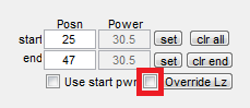 | Power to use at ending axial position of stack can be set interactively. When both Posn start and Posn end are set, user can choose to automatically or manually Override Lz, i.e. override the length constant Lz set on the Power Controls for the selected Beam, with the exponential length-constant value implied by (computed from) the start/end positions and powers. |
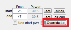 | When Posn start/end and Power start/end values are all set, the Lz (length constant) value in Power Controls can be overridden with value computed from the specified position/power endpoints.
|
Motor Alignment
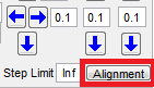 | Opens the Motor Alignment Window that allows to align the motor coordinate system to the scan coordinate system. |