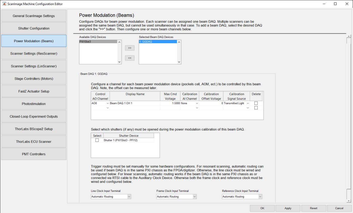
Power Modulation (Beams) Settings Panel
Daq Device Selection Settings
| Available Daq Devices | The Available Daq Device list displays the Daq devices setup on the system ScanImage is running on, and have not been move to the Selected Beam Daq Device list. |
| Selected Beam Daq Devices | The Selected Beam Daq Device list displays Daqs that have been selected. Each scanner can be assigned one Beam Daq (e.g. "PXI1Slot4"). |
| >> | The >> button moves the selected DAQ Device from the Available Device List to the Selected Beam Daq Device List. The selected device is removed from the Available Device List. |
| << | The << button moves the selected DAQ Device from the Selected Beam Daq Device List to the Available Device List. The selected device is removed from the Selected Beam Daq Device List.. |
Selected Daq Power Modulation Settings
Daq Power Modulation Settings must be entered for each Selected Beam Daq Device. The name of the selected Beam Daq Device appears in the title of the Beam Daq Panel.
Channel Settings
| Control AO Channel | Select the AO (Analog Output) Channel ID to be used for the selected beam. |
| Display Name | Enter an identifying name for the selected beam/control channel. |
| Max Cmd Voltage | Enter the voltage range to use for the selected beam/control channel. A default of 1.5 is provided. |
| Calibration AI Channel | Select the AI (Analog Input) channel to be used for the selected beam/control channel. Selecting "None" indicates that no calibration is to be performed for the selected beam/control channel. |
| Calibration Offset Voltage | Enter the calibration offset voltage for the selected beam/control channel. |
| Calibration Signal Source | Select either "Transmitted Light" or "Rejected Light" for the beam's modulation device that should be used to calibrate the transmission curve. |
| Delete | To delete a row, press the "X" on the beam/control channel row you want deleted. |
- Upon the selection of a new beam device, one default channel row is provided.
- The default entry contains th AO0 channel, with a default display name "Beam DAQ 1 CH 1", a maximum cmd voltage of 1.5, no AI calibration channel, 0 calibration offset voltage an a "Transmitted Light" calibration signal source..
- This row can be deleted.
- All columns can be edited.
Shutter and Trigger Routing Settings
| Select | Check the Select Checkbox for those Shutters you want associated with the Selected Beam Daq Device. The default is unchecked. |
| Shutter Device | This is a read-only field that displays the name of a Shutter configured on the Shutter Configuration Settings page. |
| Line Clock Input Terminal | Select the Line Clock to which the external Beam Trigger is connected. Select the "Automatic Routing" option for automatic routing using the PXI/RTSI bus. The default is "Automatic Routing". |
| Frame Clock Input Terminal | Select the Line Clock to which the Frame Clock is connected. Select the "Automatic Routing" option for automatic routing using the PXI/RTSI bus. The default is "Automatic Routing". |
| Reference Clock Input Terminal | Select the Line Clock to which the Reference Clock is connected. Select the "Automatic Routing" option for automatic routing using the PXI/RTSI bus. The default is "Automatic Routing". |
- All shutters that have been configured on the Shutter Configuration Settings page and saved will appear in the Shutters table.
- To select a shutter(s) for a beam, check the Select checkbox next to the desired Shutter Device.