Pockels Cell Setup
A Pockels Cell splits the input beam into a 'transmitted beam' and into a 'rejected beam'. The transmitted beam is used for illuminating the sample, while the energy of the rejected beam is dissipated in a beam dump. By changing the control voltage of the Pockels Cell, the power ratio between the transmitted and rejected beam can be adjusted. The Pockels Cell power modulation is non-linear in respect to the control voltage. To compensate for this non-linearity, ScanImage creates a look-up table that translates a desired power into a control voltage. To measure this look up table, a photodiode is placed either in the transmitted beam or the rejected beam. To avoid over-exposure of the photodiode, a small fraction of the beam is picked off, and a ND-filter is used to further reduce the intensity at the photodiode.

Option 1: A beam pick-off after the Pockels Cell directs light to the photodiode.
ScanImage must be configured for 'Transmitted Light'

The photodiode is positioned in the rejected beam of the Pockels Cell.
ScanImage must be configured for 'Rejected Light'
Wiring
Connect the Pockels Cell to the high voltage driver as described in the user manual. Connect the command input on the driver board to an AO (analog output) of the ScanImage system. Connect the Photodiode to an AI (analog input) on the same DAQ board as the command signal.
For a Conoptics 302(RM) driver, the switches should be set as indicated in the graphic to the right.

ScanImage requires the Conoptics 302RM driver to be set to 1kΩ impedance, non-inverting unipolar input.
ScanImage Configuration
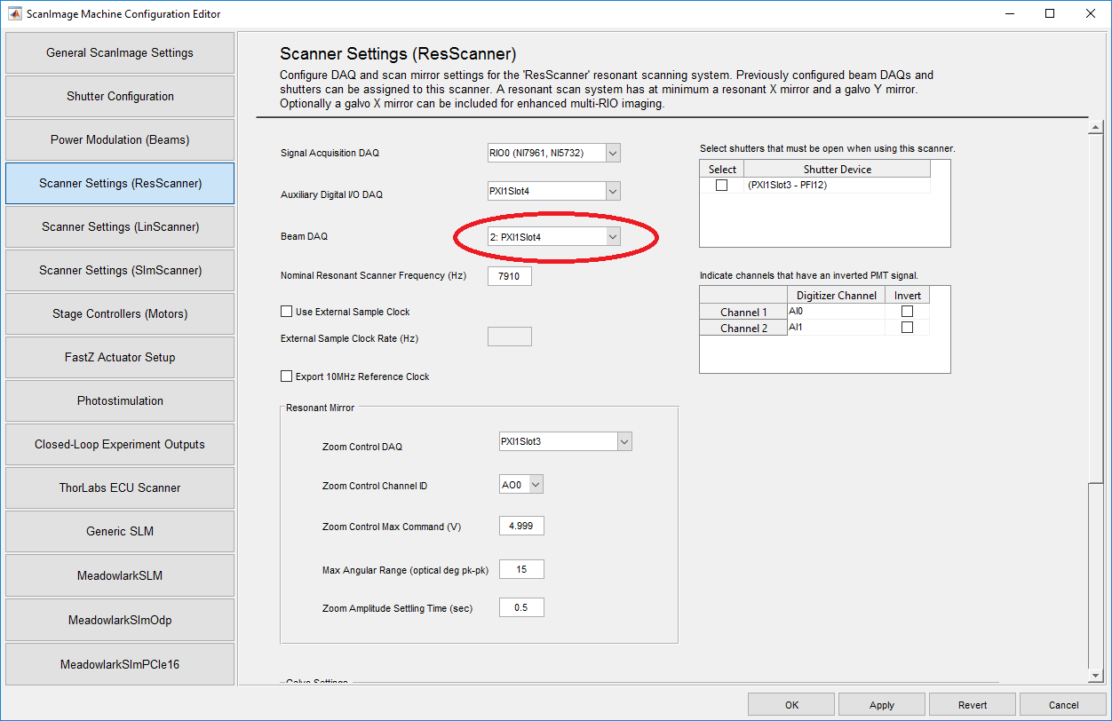
In ScanImage, open the Machine Configuration Editor by selecting 'File > Machine Configuration'. In the Power Modulation section, select one or more NI-DAQ devices, and configure the Analog Outputs and Analog Inputs for the connected Pockels Cell. Next, each configured Beam DAQ board should be assigned to a Scanner. The Scanner then uses the Beam DAQ board during imaging for power modulation.
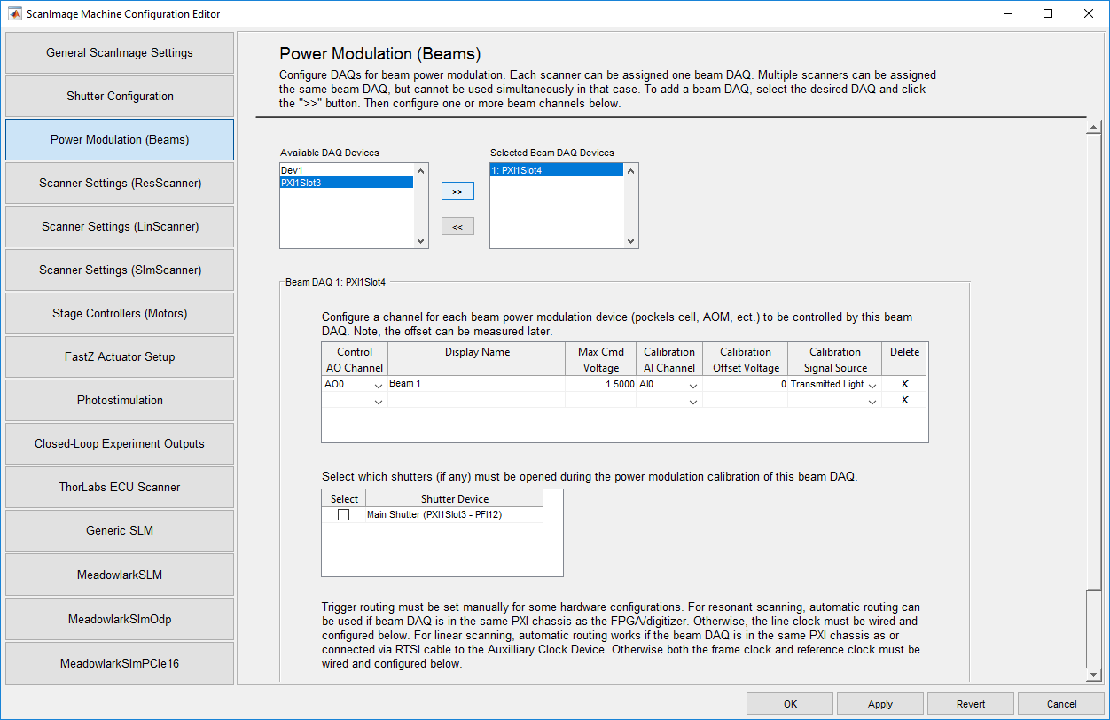
Configure the beam modulator in ScanImage by selecting 'File > Machine Configuration'
Calibration
The Pockels Cell power modulation is non-linear in respect to the control voltage. To compensate for this non-linearity, ScanImage creates a look-up table that translates a desired power into a control voltage. After the Pockels Cell is configured, follow the steps below to create a look up table.
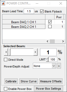
- Select which beam to calibrate
- Shutter the laser and select 'Calibrate' to measure the dark voltage of the photodiode
- Open the laser shutter and select 'Calibrate'
- Select 'Show Curve' to plot the Pockels Cell response
 A typical calibration curve after performing a beam calibration. If the calibration failed, ScanImage will print an error message and will use a linear look up table instead.
Alignment
When ScanImage is idle, the scanners are parked, the shutters are closed and the Pockels Cell does not transmit light. For alignment, select 'Point' in the ScanImage Main Controls window. This will open the shutter and center the mirrors. To allow light through the Pockels Cell, change the slider in the Power Controls window to the desired power, and check the box 'Direct Mode'. To abort the alignment, select the 'Abort' in the Main Controls. This will park the scanners, close the shutters and Pockels Cells.
Ensure hardware is functioning
Ensure ScanImage is not active. Connect the photodiode to an oscilloscope. Change the offset dial on the Pockels Cell driver board and observe if the voltage of the photodiode is changing. Ensure the photodiode is not saturating, and the output voltage does not exceed 10V. If necessary, adjust the output gain of the photodiode or change the optical density of the ND filter.
Ensure the DAQ AO is functioning
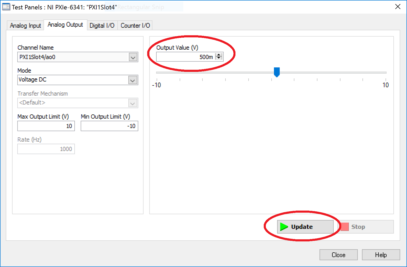
Open a NI MAX Test Panel for the DAQ board connected to the Pockels Cell driver. Open the tab 'Analog Output' and select the correct output channel. Change the output value and select 'Update' to send a constant signal to the driver. Observe on the oscilloscope if the photodiode output is changing. Ensure not to exeed the maximum voltage of the driver board input.
Ensure the DAQ AI is functioning
Reset the analog output voltage to zero. Connect the photodiode to a DAQ AI channel on the same board as the command output. In the NI Test Panel, select the tab 'Analog Input' and select the correct AI channel. Click 'Start' to update the graph. Change the offset dial on the driver and observe if the AI voltage level changes.
Close the NI Test Panel.
Check the ScanImage configuration
In ScanImage, select File > Machine Configuration and verify the settings for the Power Modulation (see above). Verify the settings for AO channel, AI channel, transmitted/rejected light, and shutters.
Calibrate the Pockel Cell in ScanImage
Follow the instruction above to obtain a calibration curve
Verify the power under the objective
In the main window, select 'Point' to center the scanner mirrors. Change the slider in the Power Control Window to 5%. Check the box 'Direct Mode' and verify that the laser reaches the objective. Uncheck the box 'Direct Mode'.
Verify the power throughput while scanning
Start a Focus in ScanImage. Verify with a powermeter that the beam power changes as you change the power in the ScanImage power controls. Abort the focus.