Galvo Controller Board Configuration
Standard Cambridge Technologies 671 series galvo controller accept two input signals:
- Galvo Position
- Galvo Position Offset
ScanImage controls the stimulation pattern using the Galvo Position signal. To correct for sample motion, ScanImage uses the Galvo Position Offset Signal, which is updated independently of the Galvo Position signal.
R124 and R93 determine the gain of the inverting amplifier shown in the figure on the right. Since NI DAQ boards can drive analog outputs +-10V, no additional amplification is required. Using the formula Vout = -Vin * R93/R124 it can be seen, that R93 and R124 should be selected to have the same value (20kOhm should be sufficient for most applications).
To determine R85, review page 13 of the Series 671 instruction manual:
R85 = ((+Offset In - -Offset In) x R54 x (R29/(R30+R119)))/(Position Output Scale Factor x Position Offset Range)
Standard values are
Offset In = 10V
R54 = 10kOhm
R29 = 10kOhm
R30 = 19kOhm
R119 = 1kOhm
Position Output Scale Factor = 0.5V /° mechanical
Choose the position Offset Range in °mechanical to select the offset range.
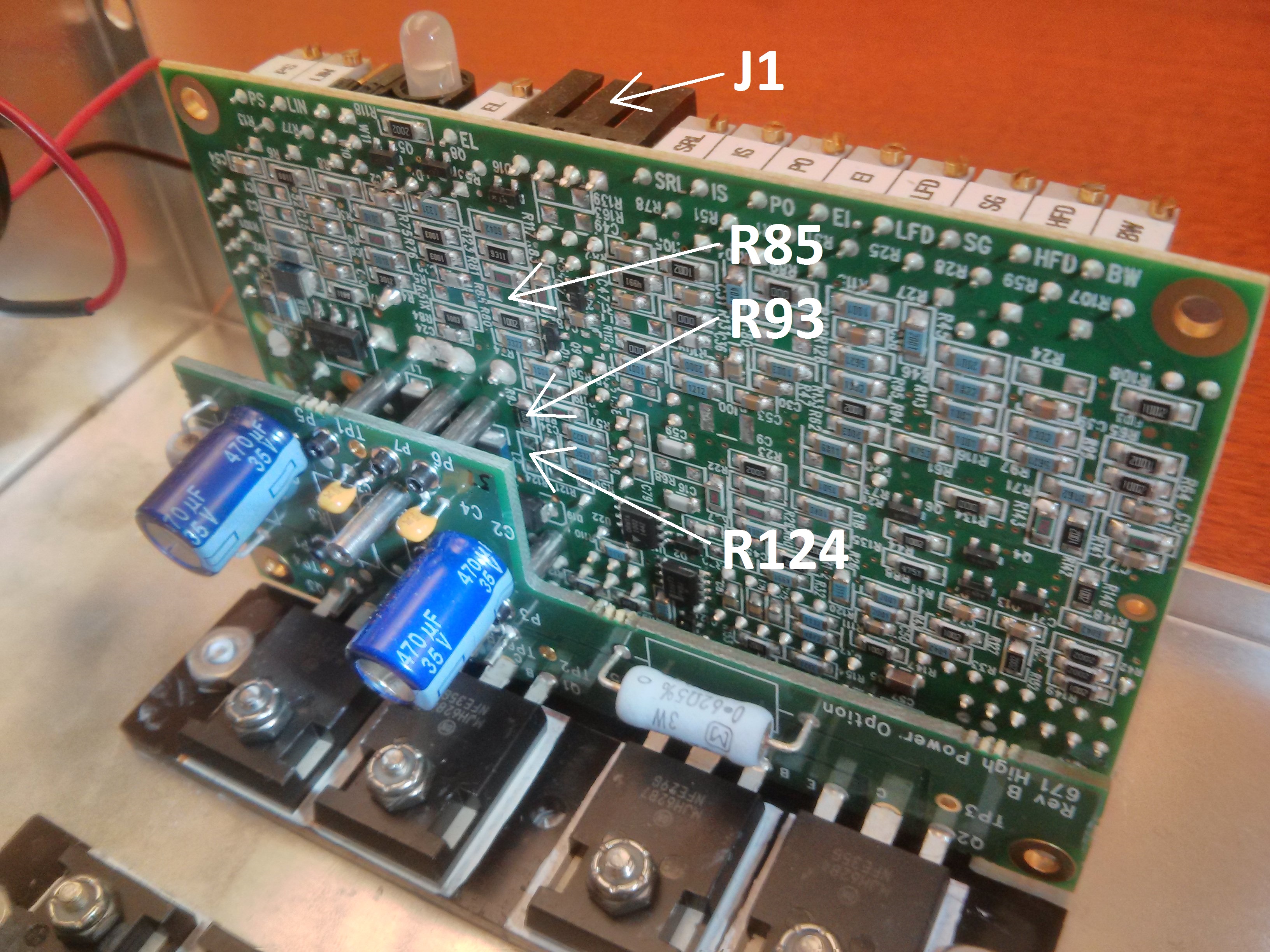
Locations of the resistors R85, R93 and R124 on a Cambridge Technologies 671 series galvo controller.

Offset input circuit of a Cambridge Technologies 671 series galvo controller. R85, R93 and R124 might be unpopulated or zero-ohm resistors. To enable the controller board's offset input, these resistors need to be added / replaced.
Wiring
To use motion correction the following signals need to be connected:
- XY Galvo Position (see Configuring LinScan)
- XY Galvo Position Offset
- XY Galvo Position Feedback
The XY Galvo Position Feedback is used to calibrate the position offset signal relative to the galvo position signal.
The galvo position and offset inputs are located on connector J1 of the Cambridge Technologies galvo controller board. Assuming these inputs are configured to be non-inverting single ended (W4 1-3 and 4-6 jumpered), the following wiring scheme can be used:
| Pin | Signal | MDF Section | MDF Variable | Recommended MDF Value |
|---|---|---|---|---|
| J1.2 (X,Y) | Signal GND | - | - | - |
| J1.3 (X) | X Galvo position | LinScan | XMirrorChannelID | 0 |
| J1.3 (Y) | Y Galvo position | LinScan | YMirrorChannelID | 1 |
| J1.4 (X) | X Galvo position offset | LinScan | XMirrorOffsetChannelID | 0 |
| J1.4 (Y) | Y Galvo position offset | LinScan | YMirrorOffsetChannelID | 1 |
| J4.2 (X) | X Galvo position feedback | LinScan | XMirrorPosChannelID | 5 |
| J4.2 (Y) | Y Galvo position feedback | LinScan | YMirrorPosChannelID | 6 |
| - | Photodiode feedback | Photostim | BeamAiId | 7 |
| J4.3 (X,Y) | Signal GND | - | - | - |
%% LinScan
deviceNameAcq   = 'PXI1Slot3';      % string identifying NI DAQ board for PMT channels input
deviceNameGalvo = 'PXI1Slot3';      % string identifying NI DAQ board for controlling X/Y galvo. leave empty if same as deviceNameAcq
deviceNameAux   = 'PXI1Slot3';      % string identifying NI DAQ board for outputting clocks. leave empty if unused. Must be a X-series board

%Scanner position feedback
XMirrorPosChannelID = 5;            % The numeric ID of the Analog Input channel to be used to read the X Galvo position (optional).
YMirrorPosChannelID = 6;            % The numeric ID of the Analog Input channel to be used to read the y Galvo position (optional).

%Scanner control
XMirrorChannelID = 0;               % The numeric ID of the Analog Output channel to be used to control the X Galvo.
YMirrorChannelID = 1;               % The numeric ID of the Analog Output channel to be used to control the y Galvo.

% (optional) Mirror position offset outputs for motion correction
deviceNameOffset = 'Dev1';          % string identifying NI DAQ board that hosts the offset analog outputs
XMirrorOffsetChannelID = 0;         % numeric ID of the Analog Output channel to be used to control the X Galvo offset.
YMirrorOffsetChannelID = 1;         % numeric ID of the Analog Output channel to be used to control the y Galvo offset.
XMirrorOffsetMaxVoltage = 1;        % maximum allowed voltage output for the channel specified in XMirrorOffsetChannelID
YMirrorOffsetMaxVoltage = 1;        % maximum allowed voltage output for the channel specified in YMirrorOffsetChannelID

%% Photostim
photostimScannerName = 'LinScan';   % Name of scanner (from first MDF section) to use for photostimulation. Must be a linear scanner
%Monitoring DAQ AI channels
BeamAiId      = 7;                  % AI channel to be used for monitoring the Pockels cell output
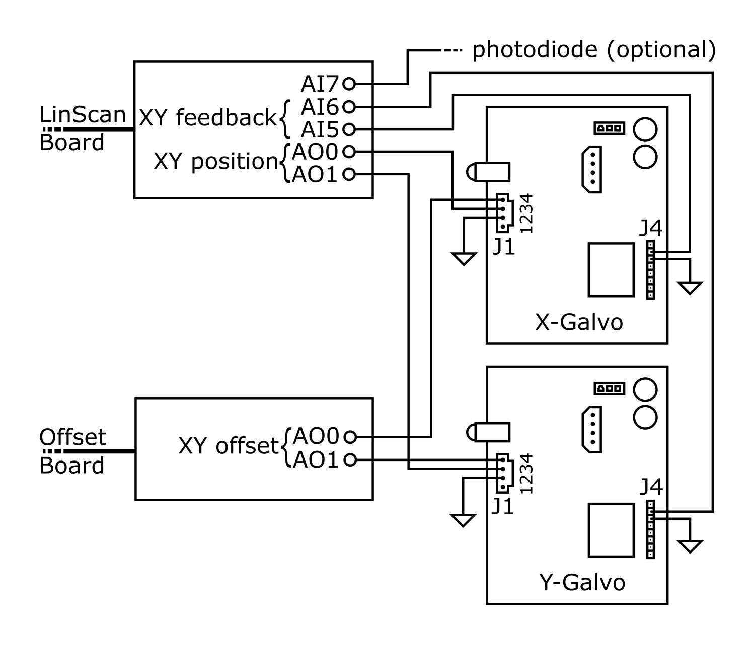
Offset correction wiring scheme of two 671 series Cambridge Technologies Galvo driver boards. To calibrate the offset output, it is essential to connect the XY position feedback signals (J4.2)
Operation
To enable sample tracking, perform the following steps:
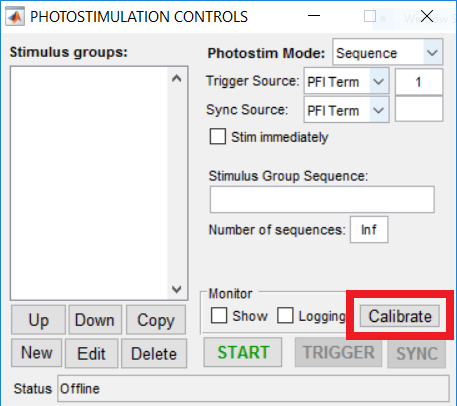
- Start the Photostimulation module by selecting 'Start' in the Photostimulation Controls window
- Start a Focus/Grab/Loop
- Right click the live image in one of the channel display windows and select 'Set motion correction reference'
- Right click the live image in one of the channel display windows and select 'Enable motion correction'
- (Optional) Right click the live image in one of the channel display windows and select 'Show motion'
- (Optional) Enable the 'Monitor Show' option in the Photostimulation Controls window
The Photostimulation module is now tracking the sample by updating the offset signal whenever motion is detected.
Calibrating the Photostim Module calibrates the galvo feedback signal and the galvo offset signal.