
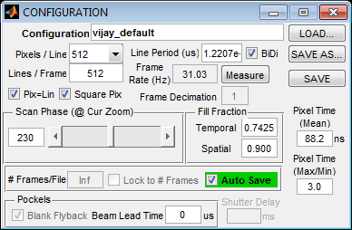
CONFIGURATION Panel
Imaging System
| Active Imaging System | Select a scanning system to use for imaging from the systems that have been configured in the Machine Data File |
| Alignment | Opens the ALIGNMENT CONTROLS panel that can be used to align parallel scanning systems |
Acquisition Parameters
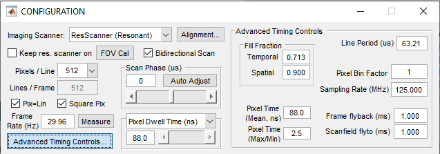
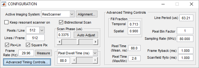
| Keep resonant scanner on | When selected, the resonant scanner is kept on even when not actively imaging |
| FOV Cal | Opens a window for adjusting the resonant scan amplitude as a percent of the max scan angle for command voltages. This feature is for resonant scanning only. |
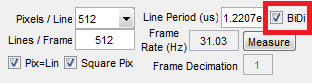
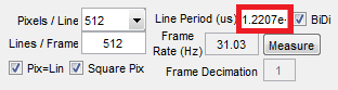
| Bidirectional Scan | Enables two way scanning (ie data is acquired when the X scan mirror is traveling in both directions). Bidirectional scanning will increase the frame rate, while unidirectional scanning can produce higher quality images by avoiding the interlace effect from the phase being slightly incorrect. |
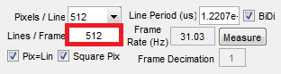
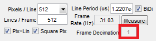
| Pixels Per Line | Imaging resolution in the fast scan mirror (X) dimension. Only applies in non multiple-ROI imaging |
| Lines Per Frame | Imaging resolution in the slow scan mirror (Y) dimension. Only applies in non multiple-ROI imaging |
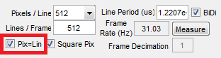
| Pix=Lin | Apply square pixelation constraint: if selected, the values of Pixels/Line and Lines/Frame are constrained to be equal, e.g 512x512, 256x256, etc.
|
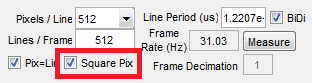
| Square Pix | Apply square pixel constraint: if selected, the value of Scan Angle Multiplier Slow on the Main Controls is constrained to match the fraction (Lines/Frame)/(Pixels/Line).
|
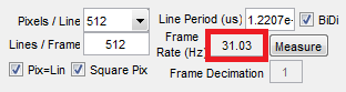
| Frame Rate (Measure) | Rate in which frames are acquired. |
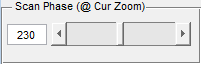
| Scan Phase Adjustment | Adjusts the timing between acquisition of forward and reverse lines for bidirectional scanning. If bidirectional scanning is on the Auto Adjust button can be used to find the correct scan phase by image analysis |
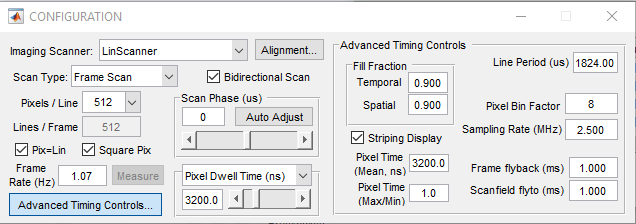
| Pixel Dwell Time/ Line Rate/ Line Period | Display/control for scanning rate. For resonant scanning this is a display only, as the scanner rate is fixed. For linear scanning, this value can be changed. The scanning rate is set by a combination of the sampling rate and pixel bin factor. |
Advanced Timing Controls Panel
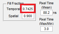
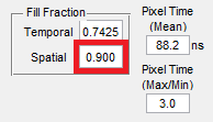
| Fill Fraction (Temporal/Spatial) | Sets the fraction of the scanned area in the fast mirror (X) dimension where image acquisition occurs |
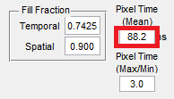
| Pixel Time (Mean) | Mean acquisition time, in ns, for each pixel. |
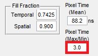
| Pixel Time (Max/Min) | Ratio of pixel dwell time at outer pixel (max) to center pixel (min) of each scanned line Resonant Scanning: Ratio is positive, as dwell time for sinusoidal scan trajectory is greater towards the field edges compared to the center Linear Scanning: Ratio is always one (1) - the pixel dwell time is uniform across the scanned line |
| Line Period | Time interval between the start of each line in the frame |
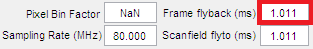
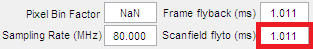
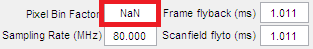
| Pixel Bin Factor | The numer of ADC samples that are averaged into one pixel. |
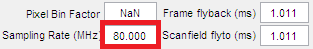
| Sampling Rate | Sets the rate that ADC samples are collected |
| Frame Flyback | The time to allow for the slow scan mirror (Y) to travel from the end position back to the start position at the end of a frame |
| Frame Flyto | For multiple ROI imaging, the time to allow for the scanner to transition from the end position of one ROI to the start position of another |
Line Scan Controls
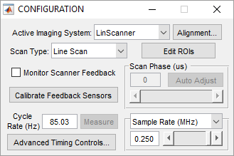
| Scan Type | If the currently selected scanning system is a linear scanner, this control appears to switch between traditional frame scanning and arbitrary line scanning. |
| Monitor Scanner Feedback | When enabled, displays (and records to disk if data logging is on) the actual scanner path during arbitrary line scanning |
| Calibrate Feedback Sensors | Calibrated the position feedback sensor for line scanning. This must be done once for position feedback to work |