Overview
In this section, experiences and information related to typical commercial galvanometer systems are described. The developers are at this time exclusively familiar with systems from Cambridge Technology (ttp://www.camtech.com) - in particular the 6210H and 6215H galvanometers, along with either a pair of 671xx servo drivers or a dual-axis 673xx servo driver.
In particular, there are four notable physical scanner limitations that should be considered when selecting and installing scanners, and configuring them for use with ScanImage:
- Settling Time: The 'small-angle' settling time is a fundamental property of a scanner system, reflecting a combination of the physical mirror inertia as well as the servo topology used for control. This limit is manifest in the acceleration and 'ripple' occurring during small commanded changes in scanner position or velocity.
- Servo Power Limit: Servo controllers provide current/power to produce scanner acceleration. There is a limit to the maximum and sustained current/power the controller can supply, and a fault condition can be generated when the commanded scan exceeds these limits.
- Slew Rate Limiting: Servo controllers typically limit the maximum velocity of the scanner, to help avoid reaching the servo's power limits as well as to avoid exciting system resonances. This limit acts as a hard clamp on the scan speed that can be achieved at particular scan-field sizes.
- Thermal Limits: Repeated acceleration during periodic line scan can cause the galvo to rise above recommended temperatures, if sufficient cooling measures are not employed.
Settling Time
The 'small-angle' settling time is a fundamental property of the scanner system. It reflects:
- The system's acceleration. For for small-angle changes - i.e. small enough that velocity (slew-rate) limiting is not encountered - this is primary determinant of time to reach new commanded position/slope
- The servo topology used, which can trade-off between the settling-time and the accuracy of the settled position
The settling time is closely related to the
Acquisition Delay
value that is measured as part of the Fast (X) Scan Optimization procedure described above.
- The measured Acquisition Delay corresponds to half the 'small-angle' settling time, according to correspondence with Cambridge Technology and based on observations of how long is required for 'ripple' to subside following a change of position or slope.
- As described in Fast (X) Scan Optimization the settling time determines a minimum recommended Scan Delay value that should be used (2 * Acquisition Delay), to ensure the scanner has settled - i.e. all 'ripple' has subsided - onto new ramp by the beginning of each line's Acquisition Period.
The settling time of a scanner system is significantly affected by the servo topology used. Servo drivers used to date have been PID Controllers, of either Class 0 or Class 1 servo topology. Class 1 servo topology implies that one integrator is used in the servo loop, while Class 0 omits the integrator.
- Class 0 provides a faster settling time to 99% of the intended position, but then small (~1%) error remains longer than with Class 1.
- Fundamentally, Class 1 servos have a potential for instability - i.e. an unbounded response to a bounded input - owing to the nature of integration. Note, however, this is unlikely given other servo controller protection circuitry.
- The tuning of the servo system affects the settling time actually achieved
See the Scanner Characterization Test Results below for discussion of typical scanner systems and the Acquisition Delay- i.e. settling time - observed for each. These tests confirm the following expected behaviors:
- Class 0 servo systems significantly reduces the Acquisition Delay, compared to Class 1
- Smaller mirror clear aperture sizes significantly reduces the Acquisition Delay
- Reducing physical mirror size further, by limiting angular range of scanner design, moderately reduces the Acquisition Delay further
- Increasing the servo current/power drive does not affect the Acquisition Delay
The 'small-angle' settling time reflects the linear (amplitude-independent) limit on scanner performance, and is associated with a linear (amplitude-independent) frequency response implying a fundamental limit on the maximal scanner frequency (i.e. minimum Nominal Ms/Line) that can be achieved by the scanner system (at any scan amplitude).
By comparison, the slew rate and current drive limits described below are nonlinear: they depend on the amplitude of the scan (i.e. its angular range), not just the shape/speed. At higher scan speeds and larger angular scan ranges, the nonlinear limits below become increasingly paramount.
Servo Power Limits
The servo controller must source voltage and current to the galvanometer to follow the commanded trajectory. If voltage and current limits, or a combined power limit, of the controller is exceeded, then servo will fail to sustain the command required to drive the scanner.
For the systems available from Cambridge Technology, encountering such a limit will cause the servo/scanner to abruptly cease scanning, and the servo's fault indicator will light (red). The servo controller protects itself from sustaining current/voltage/power output beyond its capabilities.
The Scanner Characterization Test Results below show that such power limits are encountered when using high scan speeds and/or scan amplitudes. It is observed that:
- Using a system with higher current/power drive - the 6215H galvo which is typically paired with the servo driver 'High Power Option' - becomes important when trying to reachBidirectional scans of 0.5 ms/line over angular ranges typically required for laser scanning microscope systems (at or above 15
- When using a lower current/power drive system (the 6210H system, which does not allow the 'High Power Option' servo to be used), the current/power limits appeared more prevalent with Class 1 systems compared to Class 0 systems.
Slew Rate Limit
Servo systems frequently - but not always - include a slew rate limiter component in the circuitry that limits the maximum speed of the command signal fed to the rest of the servo control circuitry. This is done to help avoid Servo Power Limits (discussed above) as well as to prevent the excitation of scanner resonances.
Slew rate limiting is a hard-threshold effect, when the scan amplitude and/or scan speed is increased so the command slope exceeds the limit, the scanner will not follow the command, as illustrated below:
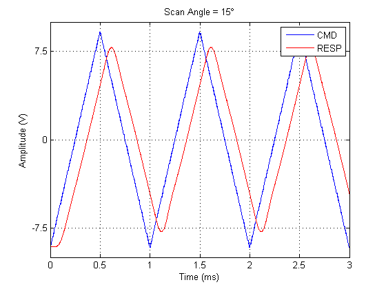
Slew rate limiting causes response (red) to not follow slope of command signal (blue)
(6210H/3mm/Class 1 system with 0.5ms/line, 15deg peak-peak Scan Amplitude, BiDi, 0.8192 Fill Frac command signal)
It is clear that slew rate limiting is a direct limiting factor on the Bidirectional scan speeds/amplitudes achieved - the slew rate slope is the greatest scan rate achievable. Note that this is Fill Fraction
independent.
For Sawtooth scans, which typically use at least a factor of 2 slower Line Period, the command slope during the Acquisition Period is not generally slew rate limited. However, the Flybackportion of the X command signal frequently does encounter this limit. This can reduce the Fill Fraction value achievable at a given scan rate ( Nominal Ms/Line), as shown here:
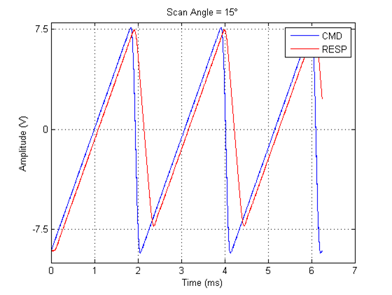
Slew rate limiting prevents flyback from reaching start of ramp – i.e. start of the Scan Delay – in sufficient time for the specified Fill Fraction
(6210H/3mm/Class 1 system with 2ms/line, 15deg peak-peak Scan Amplitude, Sawtooth, 0.787 Fill Frac command signal)
Slew rate limiting is what, in fact, makes it possible to extend the Scan Delay beyond the minimum required, to the limit of generating an X command signal with 'intantaneous' flyback, as described in Fast (X) Scan Optimization. This is found to modestly increase the Fill Fraction achievable for a given Nominal Ms/Line.
- The Slew Rate Limit can be adjusted on the servo controller, but this typically affects the servo tuning somewhat, so is not recommended for typical users.
- The Slew Rate Limit is typically adjusted to higher levels by the manufacturer for scanner systems employing higher current/power drive, such as the 6215H galvo together with the servo driver 'High Power Option'.
The Scanner Characterization Test Results below show the following quantitative results due to slew rate limits, employing manufacturer-adjusted systems:
- Bidirectional scans at the fastest supported rate (0.5ms/line) are limited to peak-peak scan amplitudes below 15 optical degrees when using lower-power systems (i.e., the 6210H) and also when using larger (6mm) clear aperture mirrors.
- Sawtooth scans of 2ms/line are significantly limited in Fill Fraction when using lower-power systems (i.e., the 6210H), in part due to the slew rate limiting as depicted above
Thermal Limits
Supplying large, sustained currents to a small physical scanner during continuous raster imaging can cause the scanner temperature to rise above the manufacuter-recommended level.
For galvanometers from Cambridge Technology, it has been advised that the galvo temperature (as measured on its shaft) be maintained below 50 deg C, to avoid gradually demagnetizing the motor core, reducing the achievable torque.
Measurements of galvo shaft temperatures under varying scan conditions were made using a Fluke 179 multimeter, and a Fluke 80BK-A temperature probe (Type-K thermocouple). Thermal compound was used at contact between thermocouple and the galvanometer shaft.
The following observations were made:
- Sawtooth scanning even at 2ms/line can cause overheating after some time, because of the rapid Flyback during each Line Period. At each scan amplitude, the optimal Fill Fractiondetermined using the standard Fast (X) Scan Optimization procedure - i.e. without stretching the Fill Fraction by reducing the Flyback time as described in Going Further - corresponded well to the limit of
Fill Fraction that could be used safely for extended/unlimited durations.
- Bidirectional scanning at 1ms/line is safe for all mirror systems tested. Bidirectional scanning at 0.5ms/line can cause overheating when used at angles typical for scanning the 'whole' field-of-view (15 optical degrees).
- Clear thresholds are crossed by increasing scan amplitude and/or scan speed, above which the temperature runs away beyond the recommended limit, and below which the temperature reaches a steady state which can be sustained indefinitely.
- Adding passive cooling to the system, e.g. by using a large metallic heatsink attached to the scanner block, increases the scan amplitude/speed achievable before crossing threshold
- Adding active cooling to the system, e.g. using liquid cooling such as with a CPU cooling system, further increases the scan amplitude/speed achievable before crossing threshold
Scanner Characterization Test Results
The Scanner Characterization Test Results below present temperatures measured at various scan speeds/amplitudes under various cooling conditions for a representative scanner system.
Scanner Limits
This section presents the maximum Fill Fraction achieved for particular scan modes/speeds, using the specified scanner systems. The Fill Fraction limit implies that higher values either:
- Cause servo to fail - indicated with
 . This implies a Current Drive limit was reached.
 - Fail to cover intended range (i.e. 2 * Scan Amplitude). This can reflect either a Settling Time and/or Slew Rate limit effect.
- Exhibit too much ripple within Acquisition Period. This implies a Settling Time limit.
 Note that this condition was determined simply 'by eye'
In addition, situations where Bidirectional scans are limited by Slew Rate, which depends on the scan amplitude/speed, but not on the Fill Fraction, are also noted in the table:
 : Severe slew rate limiting prevents this scan angle/speed, for any Fill Fraction. No Fill Fraction limit value is given, as scanning in this regime is impossible.
- : Modest slew rate limiting will affect image quality at this scan angle/speed (for any Fill Fraction). The Fill Fraction limit value is given, nonetheless, as slew rate artifact may be deemed acceptable.
Sawtooth, 2ms/line
System | 20° | 18° | 15° | 12.5° | 10° | 9° | 7.5° | 6.25° | 5° |
|---|---|---|---|---|---|---|---|---|---|
6210H, Class 0, 3mm | .706 | .731 | .759 | .787 | .787 | .819 | .819 | .819 | .819 |
6210H, Class 1, 3mm | <.706 | <.706 | .706 | .731 | .731 | .731 | .759 | .759 |
|
6215H, Class 1, 3mm | .787 | .819 | .819 | .819 | .819 | .819 | .819 | .819 | .819 |
6215HM40, Class 1, 6mm | .706 | .706 | .731 | .731 | .731 | .731 | .731 | .731 |
|
6215HM40, Class 0, 5mm, |
|
| .731 |
|
|
|
|
|
|
Bidirectional, 1ms/line
System | 20° | 18° | 15° | 12.5° | 10° | 9° | 7.5° | 6.25° | 5° |
|---|---|---|---|---|---|---|---|---|---|
6210H, Class 0, 3mm | .819 | .819 | .819 | .819 | .819 | .819 | .819 | .819 | .819 |
6210H, Class 1, 3mm | .819 | .819 | .819 | .819 | .819 | .819 | .819 | .819 | .819 |
6215H, Class 1, 3mm | .819 | .819 | .819 | .819 | .819 | .819 | .819 | .819 | .819 |
6215HM40, Class 1, 6mm | .819 | .819 | .819 | .819 | .819 | .819 | .819 | .819 | .819 |
6215HM40, Class 1, 5mm, |
|
|
|
|
|
|
|
|
|
Bidirectional, 0.5ms/line
System | 20° | 18° | 15° | 12.5° | 10° | 9° | 7.5° | 6.25° | 5° |
|---|---|---|---|---|---|---|---|---|---|
6210H, Class 0, 3mm |
|
|
|
| .819 | .819 | .819 | .819 | .819 |
6210H, Class 1, 3mm | <.706 | <.706 | <.706 | <.706 | .706 | .731 | .819 | .819 | .819 |
6215H, Class 1, 3mm | .819 | .819 | .819 | .819 | .819 | .819 | .819 | .819 | .819 |
6215HM40, Class 1, 6mm |
|
|
| .819 | .819 | .819 | .819 | .819 | .819 |
6215HM40, Class 0, 5mm, |
|
| .819 | .819 | .819 | .819 | .819 | .819 | .819 |
Systems Tested
System | Optical Angular Range | Typical | Command Input Scale | Notes |
|---|---|---|---|---|
6210H, Class 0, 3mm | 60° | 60 | 0.667 V/° (mechanical) |
|
6210H, Class 1, 3mm | 60° | 90 | 0.667 V/° (mechanical) |
|
6215H, Class 1, 3mm | 60° | 90 | 0.667 V/° (mechanical) |
|
6215HM40, Class 1, 6mm | 40° | 120 | 1.0 V/° (mechanical) |
|
6215HM40, 20deg, Class 0, 5mm | 20° | 100 | 2.0 V/° (mechanical) | Special system, configured for '3mm' inertia due to |
Thermal Limits
To illustrate the dependence of temperature on scan amplitude, scan speed, and cooling measures, below is presented the duration of continuous Bidirectional scanning required to reach 50 degC, or the temperature measured after 1 hour.
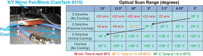
- These measurements were obtained with a 6215H/Class 0/5mm system, specially configured with a reduced full angular scan range of 20 optical degrees:
- Adding cooling measures increases the optical angular range achieved before reaching the thermal threshold when using 0.5ms/line Bidirectional scanning
- Active cooling employed a CPU liquid cooling system (a cooling element, attached to underside of galvo block, and recirculator).
- When using 1ms/line Bidirectional scanning, no cooling measures are required