FastZ Actuator Settings Panel
Fast Z Actuator Settings
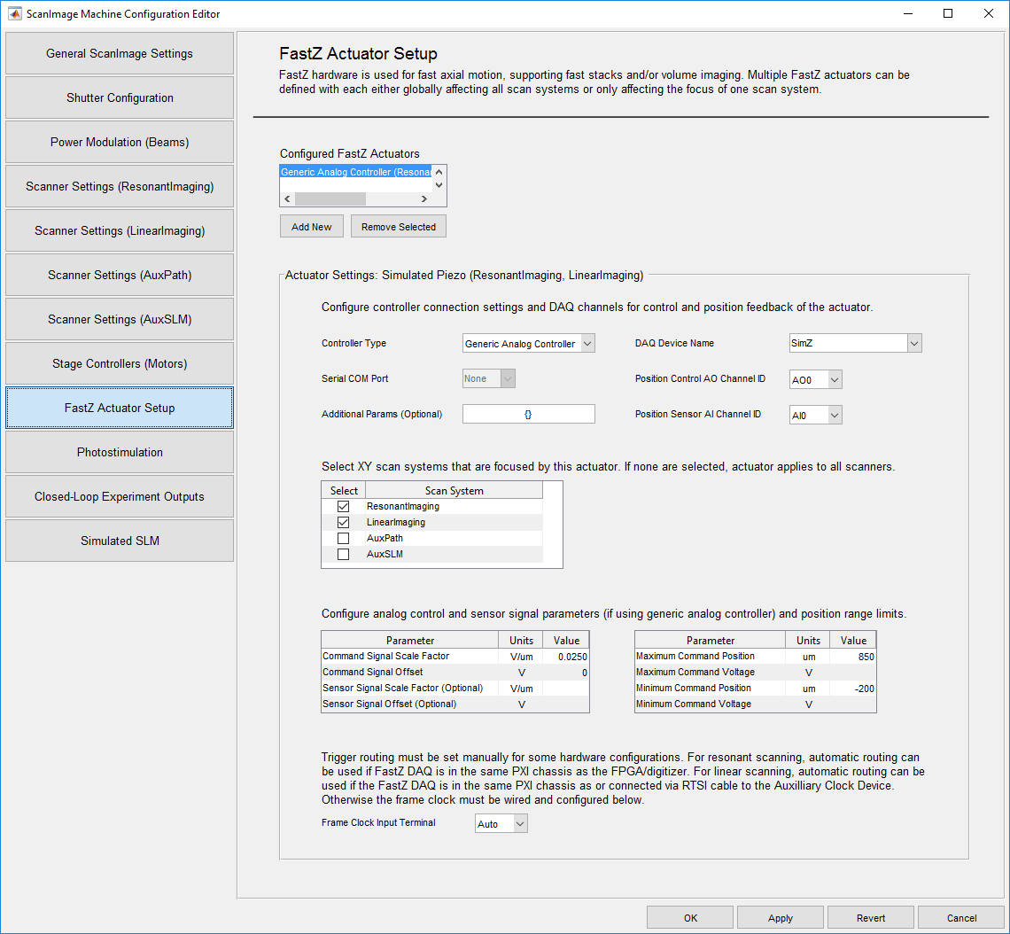
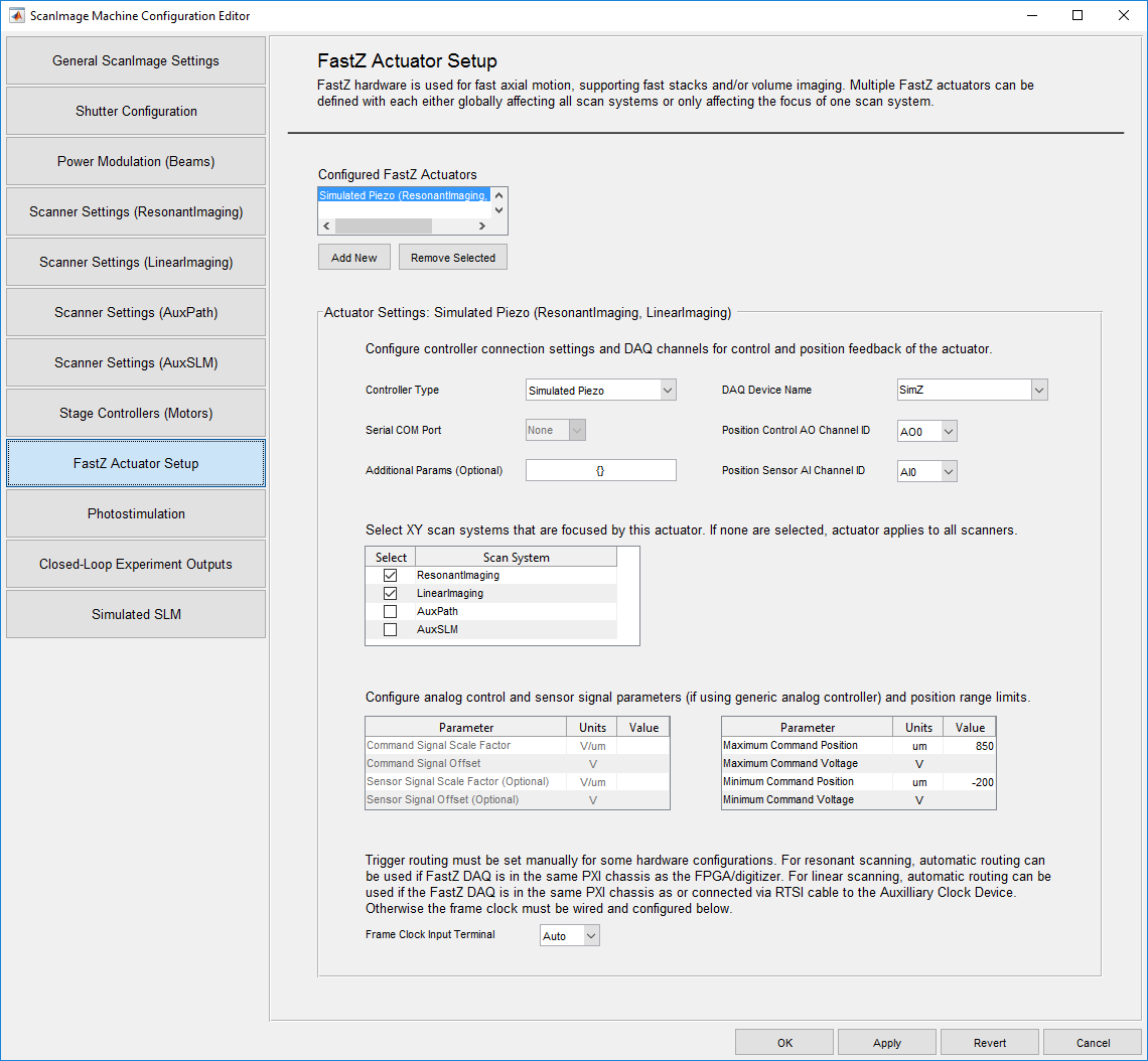
ScanImage allows you to configure multiple Fast Z actuators. Each actuator can be configured as affecting all scan paths (such as a piezo that moves the objective lens) or only applying to certain scan paths (such as a remote focus mirror in one scan path). The following parameters can be configured for each Fast Z actuator:
| Controller Type | Select the Fast Z Controller from the list of controllers supported by ScanImage. |
| Serial COM Port | If using serial communication, select the COM port to be used for the Fast Z Controller. |
| Additional Params | Some Fast Z controllers have additional optional or required parameters. These should be entered as a cell array of property-value pairs. Ex: {'baudRate' 9600} |
| DAQ Device Name | Select the DAQ device used for the position control and feedback signals. |
| Position Control AO Channel ID | Select the Analog Output (AO) channel used for the Fast Z Controller. |
| Position Sensor AI Channel ID | Select the Analog Input (AI) channel used for the Fast Z Sensor. |
| Scan Systems | Put a check next to each XY scan path that is affected by this Fast Z actuator. If none are checked, the actuator is assumed to affect all scan paths. Each XY scan path can only have one Fast Z actuator assigned to it. |
| Command Signal Scale Factor | Specify the conversion factor from microns to voltage for the position command signal. This option is only available if the generic analog controller is selected. Otherwise this option is grayed out, as the controller type provides this information. |
| Command Signal Offset | Specify the offset voltage for the position command signal. This option is only available if the generic analog controller is selected. Otherwise this option is grayed out, as the controller type provides this information. |
| Sensor Signal Scale Factor | Specify the conversion factor from microns to voltage for the position sensor signal. If left blank it can be measured later. This option is only available if the generic analog controller is selected. Otherwise this option is grayed out, as the controller type provides this information. |
| Sensor Signal Offset | Specify the offset voltage for the position sensor signal. If left blank it can be measured later. This option is only available if the generic analog controller is selected. Otherwise this option is grayed out, as the controller type provides this information. |
| Maximum Command Position | Specify upper limit of position command in microns |
| Maximum Command Voltage | Specify upper limit of position command in voltage |
| Minimum Command Position | Specify lower limit of position command in microns |
| Minimum Command Voltage | Specify lower limit of position command in voltage |
| Frame Clock Input Terminal | Select the input terminal to which the external frame trigger is connected. |