Pockels Cell Setup
A Pockels Cell splits the input beam into a 'transmitted beam' and into a 'rejected beam'. The transmitted beam is used for illuminating the sample, while the energy of the rejected beam is dissipated in a beam dump. By changing the control voltage of the Pockels Cell, the power ratio between the transmitted and rejected beam can be adjusted. The Pockels Cell power modulation is non-linear in respect to the control voltage. To compensate for this non-linearity, ScanImage creates a look-up table that translates a desired power into a control voltage. To measure this look up table, a photodiode is placed either in the transmitted beam or the rejected beam. To avoid over-exposure of the photodiode, a small fraction of the beam is picked off, and a ND-filter is used to further reduce the intensity at the photodiode.
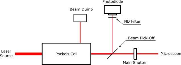
Option 1: A beam pick-off after the Pockels Cell directs light to the photodiode.
ScanImage must be configured for 'Transmitted Light'
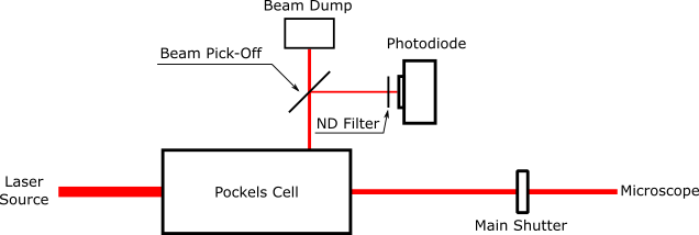
The photodiode is positioned in the rejected beam of the Pockels Cell.
ScanImage must be configured for 'Rejected Light'
ScanImage Configuration
In ScanImage, open the Machine Configuration Editor by selecting 'File > Machine Configuration'. In the Power Modulation section, select one or more NI-DAQ devices, and configure the Analog Outputs and Analog Inputs for the connected Pockels Cell. Next, each configured Beam DAQ board should be assigned to a Scanner. The Scanner then uses the Beam DAQ board during imaging for power modulation.
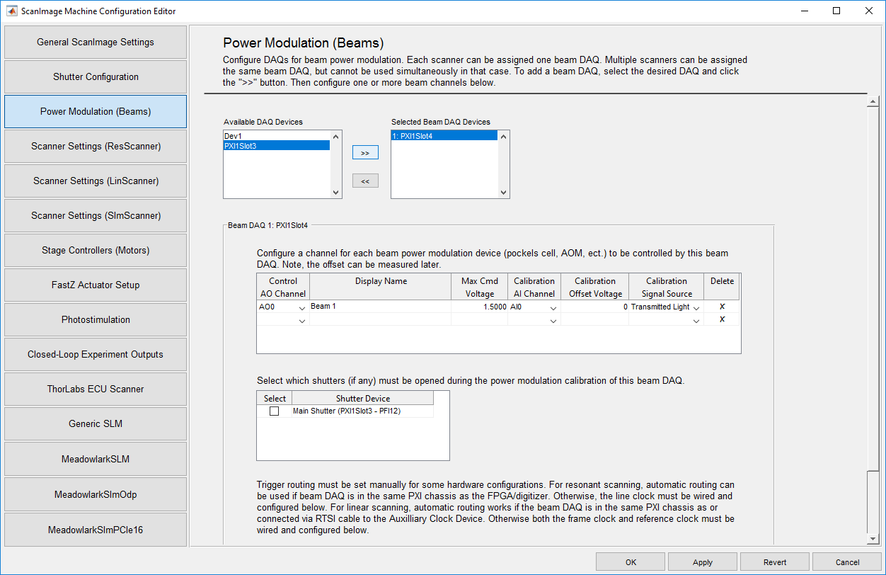
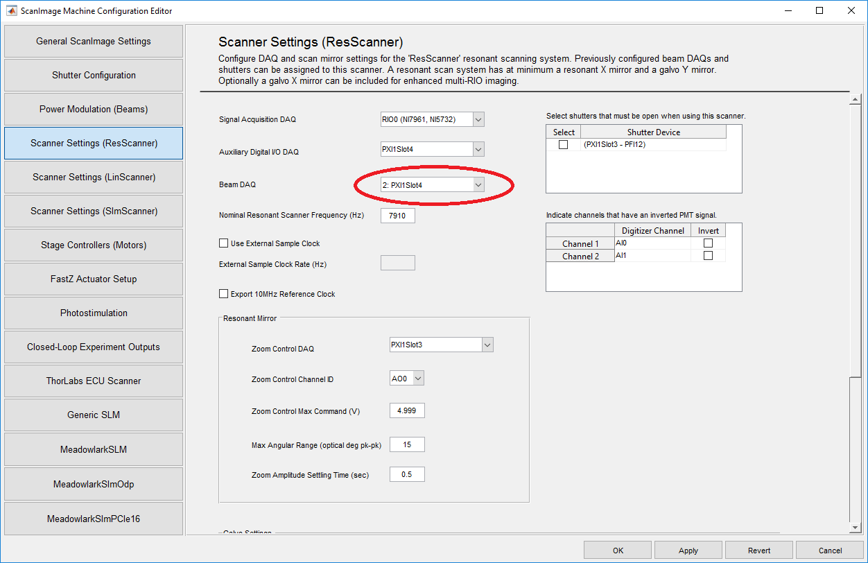
Configure the beam modulator in ScanImage by selecting 'File > Machine Configuration'
Calibration
The Pockels Cell power modulation is non-linear in respect to the control voltage. To compensate for this non-linearity, ScanImage creates a look-up table that translates a desired power into a control voltage. After the Pockels Cell is configured, follow the steps below to create a look up table.
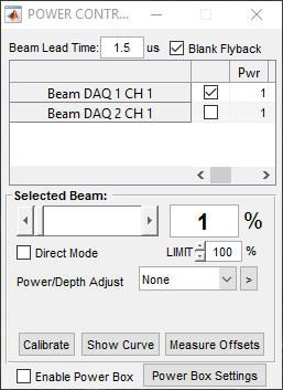
- Select which beam to calibrate
- Shutter the laser and select 'Calibrate' to measure the dark voltage of the photodiode
- Open the laser shutter and select 'Calibrate'
- Select 'Show Curve' to plot the Pockels Cell response
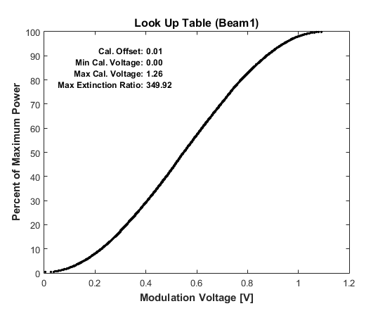 A typical calibration curve after performing a beam calibration. If the calibration failed, ScanImage will print an error message and will use a linear look up table instead.
Alignment
When ScanImage is idle, the scanners are parked, the shutters are closed and the Pockels Cell does not transmit light. For alignment, select 'Point' in the ScanImage Main Controls window. This will open the shutter and center the mirrors. To allow light through the Pockels Cell, change the slider in the Power Controls window to the desired power, and check the box 'Direct Mode'. To abort the alignment, select the 'Abort' in the Main Controls. This will park the scanners, close the shutters and Pockels Cells.
